background image

34

Gas End Opera

ting


Instructi

ons

1.

2.

gas supply.

3.

4.

GENERAL USE OF THE GRILL

USING THE GRILL

Lig

htin

g Instruc

ti

ons

WARNING: IMPORTANT!

BEFORE LIGHTING

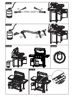
TO LIGHT THE MAIN BURNER

LIGHTING INSTRUCTIONS:

Open lid before lighting.

Check control knobs are all OFF and then turn on the 

Push and turn the knob slowly to HIGH. The burner 
should ignite within three attempts.

If burner does not ignite, turn the knob to OFF, wait 5 
minutes and then repeat step 3.

WARNING

CAUTIONS

Each  main  burner  is  rated  at 10,000 BTU/HR.  The  main  grill 
burners encompass the entire cooking area and are side ported to 
minimize blockage from falling grease and  debris. The knobs are 
located on  the  lower center  portion of  the control panel. Each 
knob is labeled on the control panel.    

DO NOT LEAVE THE GRILL UNATTENDED WHILE COOKING. 

NOTE: The hot grill sears the food, sealing in the juices. The more 
thoroughly  the grill is preheated, the faster the meat browns and 
the darker the grill marks.  

Grilling requires high heat for searing and proper browning. Most 
foods are cooked at the “HIGH” heat setting for the entire cooking 
time. However, when  grilling large pieces of meat or poultry, it 
may be necessary to turn the heat to the lower setting after the 
initial browning. This cooks the food through without burning the 
outside.  Foods  cooked for  a  long  time  or  foods  basted  with  a 
sugary marinade may need the lower heat setting near the end of 
the cooking time. 
NOTE: This grill is designed to grill efficiently without the  use of 
lava rocks or briquettes of any kind. Heat is radiated by the  flame 
tamers positioned above each burner.        

Inspect the gas supply hose prior to turning the gas “ON”. If there is 
evidence of cuts, wear, or abrasion, it must be replaced prior to 
use. Do not use the grill  if the odor  of gas is present. Only the 
pressure  regulator  and  hose  assembly  supplied with  the  unit 
should be used. Never substitute regulators and hose assembly 
for those supplied with  the  grill. If a  replacement is necessary, 
contact the manufacturer for proper replacement. The replace-
ment must be that specified in the manual.      

Make sure all knobs are off then turn on the gas supply from the 
LP (Liquid Propane) tank. Always keep your face and body as far 
from the grill as possible when lighting.  

Always keep your face and body as far away from the burner 
as possible when lighting. 

Keep a spray bottle of soapy water near the gas supply valve 
and check the connections before each use. 

Do not attempt to light the grill if odor of gas is present. Call for 
service 1-866-206-0888

Each burner is adjusted prior to shipment; however, variations 
in the local gas supply may make minor adjustments necessary.  

Place dust cap on cylinder valve outlet when the cylinder is not 
in use. Only  install the type  of dust cap on the cylinder valve 
outlet that is provided with the cylinder valve. Other types of 
caps or plugs may result in leakage of propane. The gas must be 
turned off at the supply cylinder when the unit is not in use.
If the appliance is stored indoors the cylinder must be discon-
nected and removed  from the  appliance.  Cylinders  must  be 
stored outdoors in a well-ventilated area out of the reach of 
children.        

Summary of Contents for DH122212-W

Page 1: ...CTION MANUAL FOR OUTDOOR USE ONLY PLEASE READ INSTRUCTIONS CAREFULLY BEFORE ASSEMBLY RETAIN THIS MANUAL FOR FUTURE REFERENCE If you have any or problems you can our customer service at from 8 00am to 4 30pm eastern Monday through Friday for assistance DO NOT RETURN TO THE PLACE OF PURCHASE ...

Page 2: ...arts Grill Hints Limited Warranty 39 40 41 41 Parts Assembly Instructions List with graphic Exploded View 08 09 17 42 Safety Instruction Gas Hook Up Installer Final Check List Leak Testing Gas End Operating Instructions Component Identification Care And Maintenance 03 32 32 33 34 35 36 ...

Page 3: ... ven lated area Household use only Do not operate this grill for other than its intended use Never use grill on a wooden surface or other flammable surfaces Use grill only on a hard stable surface that can support the grill s weight Keep 10 feet of clearance between grill and any combus ble materials when grill is in use including but not limited to bushes shrubs trees leaves grass wooden decks or ...

Page 4: ...10 ft of any structure combustible material or other gas cylinder 3 Never operate this appliance within 7 62 m 25 ft of any flammable liquid 4 Do not fill cooking vessel beyond maximum fill line 5 Heated liquids remain at scalding temperatures long after the cooking process Never touch cooking appliance until liquids have cooled to 45 C 115 F or less 6 This appliance is not intended for and should ne...

Page 5: ... and Propane Installation Code and the National Electrical Code ANSI NFPA 70 Correct LP Gas Tank Use LP gas grill models are designed for use with a standard 20 lb Liquid Propane Gas tank not included with grill Never connect your gas grill to an LP gas tank that exceeds this capacity NOTE The normal flow of gas through the regulator and hose assembly can create a humming noise A low volume of nois...

Page 6: ...rom the grill as possible Burner adjustmentshould only be performed after the burner have cooled Your grill will get very hot Never lean over the cooking area while using your grill Do not touch cooking surfaces grill housing lid or any other grill parts while the grill is in operation or until the gas grill has cooled down after use Failure to comply with these instructions may result in serious ...

Page 7: ... LINE TO THE APPLIANCE USE THE REGULATOR HOSE ASSEMBLY SUPPLIED This is a liquid propane configured grill Do not attempt to use a natural gas supply unless the grill has been reconfigured for natural gas use Total gas consumption per hour of this grill with all burners on HIGH This outdoor cooking appliance is not intended to be installed in or on boats And other recreational vehicles DO NOT USE ALU...

Page 8: ...08 EXPLODED VIEW ...

Page 9: ...oal grill hood assembly warming rack cooking grid charcoal tray left shift system fix bracket charcoal tray support bracket shaft assembly shift system support rod 2 1pc 12221202 3 1pc 12221203 4 2pcs 12221204 5 4pcs 12221205 6 1pc 12221206 7 1pc 12221207 8 2pcs 12221208 9 1pc 12221209 10 1 pc 12221210 ...

Page 10: ...fix bracket upper hood hinge lower hood hinge fire box assembly charcoal door charcoal door hinge butterfly damper gear plate side shelf 12 1pc 12221212 13 4pcs 12221213 14 4pcs 12221214 15 1pc 12221215 16 1pc 12221216 17 2pcs 12221217 18 1pc 12221218 19 1pc 12221219 20 1 pc 12221220 ...

Page 11: ...c 12221223 24 1pc 12221224 25 2pcs 12221225 26 2pcs 12221226 27 1pc 12221227 28 1pc 12221228 29 1pc 12221229 30 1 pc 12221230 charcoal tray lever large pipe plug right rear leg right front leg cart crossbeam wheel axle bottom shelf griddle storage lower bar griddle ...

Page 12: ...g lever trim charcoal door handle grease cup support grease cup castor gas tank support No Part Image QTY Part 31 1pc 12221231 32 2pcs 12221232 33 1pc 12221233 34 1pc 12221234 35 1pc 12221235 36 1pc 12221236 37 2pcs 12221237 38 1pc 12221238 39 2pcs 12221239 40 1 pc 12221240 ...

Page 13: ... 43 1pc 12221243 44 1pc 12221244 45 1pc 12221245 46 1pc 12221246 47 1pc 12221247 48 2pcs 12221248 49 4pcs 12221249 50 1 pc 12221250 left front leg left rear leg hose hook gas tank hook cat handle regulator hose lighting rod ash pan handle spacers grease tray ...

Page 14: ...cs 12221256 57 2pcs 12221257 58 4pcs 12221258 59 2pc 12221259 60 61 62 63 1pc 2pcs 2pcs 12221260 12221261 12221262 12221263 control panel knob spacers knob valve assembly burner flame tamer fire box clapboard top panel hood handle spacers lid decorative plate gas grill hood assembly badge NO ASSEMBLY REQUIRED temp gauge ...

Page 15: ...s 5pcs F 1pc 2pcs G 1pc H 5pcs I 1pc J K L M 1pc 2pcs 1pc M4 12 screw M5 18 screw M6 12 SUS screw M6 18 shoulder screw spring M6 22 screw M6 SUS nut M6 lock nut M6 cap nut M8 SUS lock nut M6 SUS spring washer HARDWARE KIT D M6 12 screw M10 lock nut ...

Page 16: ...roduct make sure all are parts present Inspect contents of box to make sure all parts are included and not damaged If any part is missing or damaged do not attempt to assemble the product NOTE Some parts with screws pre installed Loosen and tighten for final assembly Estimated Assembly Time 1 hour by two people No Part Image QTY N O 1pc 2pcs M8 SUS spring washer M6 washer ...

Page 17: ... IMPORTANT ASSEMBLE ON FLAT AND SOFT SURFACE TO AVOID SCRATCHING 1 Fasten castors 39 to the left front leg 41 and left rear leg 42 2 Use 8 pcs of D screw to attach legs to each corner of the fire box as shown D M6 12 screw X 8 ...

Page 18: ...18 3 Use 4 pcs of D screw to attach bottom shelf 28 to the 4 legs 4 Use 4 pcs of D screw to attach cart crossbeam 25 to left legs D M6 12 screw X 4 D M6 12 screw X 4 ...

Page 19: ...se 4 pcs of D screw to attach cart crossbeam 25 to right legs 6 Thread axle 28 through the wheels 26 right rear leg and right front leg and then fasten with L nut as shown D M6 12 screw X 4 L M10 lock nut X 2 ...

Page 20: ...20 7 Use 2 pcs of D screw to attach griddle storage lower bar 29 to right legs 8 Use 2 pcs of D screw to attach griddle storage uppper bar 31 to right legs D M6 12 screw X 2 D M6 12 screw X 2 ...

Page 21: ...r handle 36 to charcoal door with trim 35 and door locking lever 34 according to the diagram as shown 10 Thread the chimney assembly 2 from inner to outside of charcoal grill hood and then use 3 pcs of D screw and I nut to attach chimney to hood use G spring and J cap nut to fasten chimney cover 1 to chimney according to the diagram as shown ...

Page 22: ...SUS spring washer X 1 11 Use 1 pcs of C crew and H nut and M spring washer to attach butterfly damper 18 to fire box right side panel according to the diagram as shown 12 Use 4 pcs of D screw to attach charcoal tray and shaft assembly to the fire box back panel as shown ...

Page 23: ... O M6 washer X 2 13 Thread charcoal tray lever 21 through gear hole and then use 2 pcs of F screw with O washer and I nut to fasten it to shaft assembly according to the diagram as shown 14 Use 4 pcs of A screw to attach grease cup support 37 to grease tray ...

Page 24: ...Fasten the handles 48 and spacers 49 to ash pan and grease tray with 2 pcs of B screw on each side And then insert ash pan and grease tray to bottom of fire box as shown 16 Insert grease cup 38 to bottom of grease tray as shown ...

Page 25: ...o leave the screws head protruding approximately 1 5 inch Hang the side shelf brackets onto the protruding bolt heads and then fully tighten screws as shown Insert 2 pcs pf E screw into the lower holes of side shelf bracket and fully tighten screws as shown below 18 Insert flame tamer 56 inside fire box as shown below ...

Page 26: ...26 19 Insert cart handle 45 to left legs hole as shown below 20 Place cooking grid 5 inside fire box as shown below ...

Page 27: ...27 21 Place griddle 30 into storage bar as shown below 22 Install the warming rack 4 as shown ...

Page 28: ...8 24 Thread hose through hose hook 43 then fasten it to left front leg with 1 pcs of D screw E M6 18 shoulder screw X 1 D M6 12 screw X 1 23 Fasten lighting rod 46 to left front leg with 1 pcs of E screw ...

Page 29: ...29 25 Install gas tank hook 44 as shown below 1 2 3 ...

Page 30: ...30 26 Assembly is completed ...

Page 31: ...Always keep FRONT mark on front of the fire box and using griddle on gas grill left side Don t remove the flame tamers when using griddle to avoid grease drip to the holes on the grease tray CAUTION ENSURE THAT THE GAS SUPPLY AND THE KNOBS ARE IN THE OFF POSITION MAKE SURE THE RANGE TOP BURNER IS COOL BEFORE REMOVAL ...

Page 32: ...the L P gas supply cylinder please follow the steps below 1 2 Make sure tank valve is in its full off position turn clockwise to stop Check tank valve to assure it has proper external male threads type 1 connection per ANSIZ21 81 Minimum clearance from sides and back of unit to combustible construction 91 cm 36 in from sides and 91 cm 36 in from back All internal packaging removed Knobs turn freely...

Page 33: ...ke sure the L P cylinder is 80 full Only those parts recommended by the manufacturer should be used on the grill Substitution will void the warranty Do not use the grill until all connections have been checked and do not leak Each grill burner is tested and adjusted at the factory prior to shipment however variations in the local gas supply may make it necessary to adjust the burners The flames of ...

Page 34: ...ut the use of lava rocks or briquettes of any kind Heat is radiated by the flame tamers positioned above each burner Inspect the gas supply hose prior to turning the gas ON If there is evidence of cuts wear or abrasion it must be replaced prior to use Do not use the grill if the odor of gas is present Only the pressure regulator and hose assembly supplied with the unit should be used Never substitu...

Page 35: ...rol Knob 1 If the burner will not light after several attempts then the burner can be match lit before using the match allow 5 minutes for any accumulated gas to dissipate 2 Clip a match on one end of the lighting rod 3 Light match 4 Hold lighting rod and insert lighted match right next to the burner ports 5 Push and turn the designated control knob to HIGH 6 Burner should ignite immediately ...

Page 36: ...re disposal Keep container a safe distance from combustible materials Wet the surfaces beneath and around the grill to extinguish any ashes or coals that may have fallen out of grill To prevent excessive rust clean grill after each use cover and store in a dry place Add lubricant to the end of crank handle after using the grill every 2 3 times to make sure the handle is lifting the charcoal tray s...

Page 37: ...ore lighting the fire open the hood of your CHARCOAL GRILL as well as all of the butterfly dampers and remove the cooking grates Do not build too large a fire We recommend starting a fire with no more than 2 pounds of charcoal approximately 30 briquettes and adding more as needed during cooking but the total maximum charcoal required should be less than 5 pounds After allowing the fire to burn down pla...

Page 38: ...d much longer cooking times Slow smoking is actually a way to cure meats rather than cook them Slow smoking is ideal for turkeys chick ens beef briskets cheese and sausage Slow smoking uses temperatures that range from 140 F to 225 F Most slow smoking recipes call for the use of saline brine that helps preserve the meat and avoid bacterial contamination during the cooking process The temperature g...

Page 39: ... mild detergent and warm water solution A small amount of sand may be placed in bottom of grease tray to absorb the grease Check the grease tray frequently do not allow excess grease to accumulate and overflow out of the grease tray Warning If you wish to replace main burner we strongly recommend that you hire a professionallytrained technician to replace it Please understand that we will not be re...

Page 40: ...r an extended period of time High setting Use this setting for fast warm up for searing steaks and chops and grilling Low setting Use this setting for all roasting baking and when cooking very lean cuts such as fish These temperatures vary with the outside temperature and the amount of wind Cooking with in direct Heat You can cook poultry and large cuts of meat slowly to perfection on one side of t...

Page 41: ...neness of meat whether rare medium or well done is affected to a large degree by the thickness of the cut Expert chefs say it is impossible to have a rare doneness with a thin cut of meat The cooking time is affected by the kind of meat the size and shape of the cut the temperature of the meat when cooking begins and the degree of doneness desired When defrosting meats it is recommended that it be d...

Page 42: ...w the limitation or exclusion of incidental or consequential damages so the above limitations or exclusions may not apply to you This warranty gives you specific legal rights and you may also have other rights that vary from state to state DO NOT RETURN TO STORE For service regarding this warranty call our Customer Service Department at 1 866 206 0888 from 8 00am to 4 30pm eastern time Monday throu...

Reviews: