


TTX Series DC Actuator Installation & Maintenance Instructions |
21
www.exlar.com
| 952.500.6200
output to reduce interference from noise or differences in
ground potential between opposite ends of the signals.
See Expert Software Manual for information on how to
configure the analog output, analog motion, and related
parameters.
Single Point
Panel
Ground
External Controller
Single Point
Panel
Ground
Ground on
Power
Connector
GND
IO Com
+V
-V
+
-
-V
+V
+
-
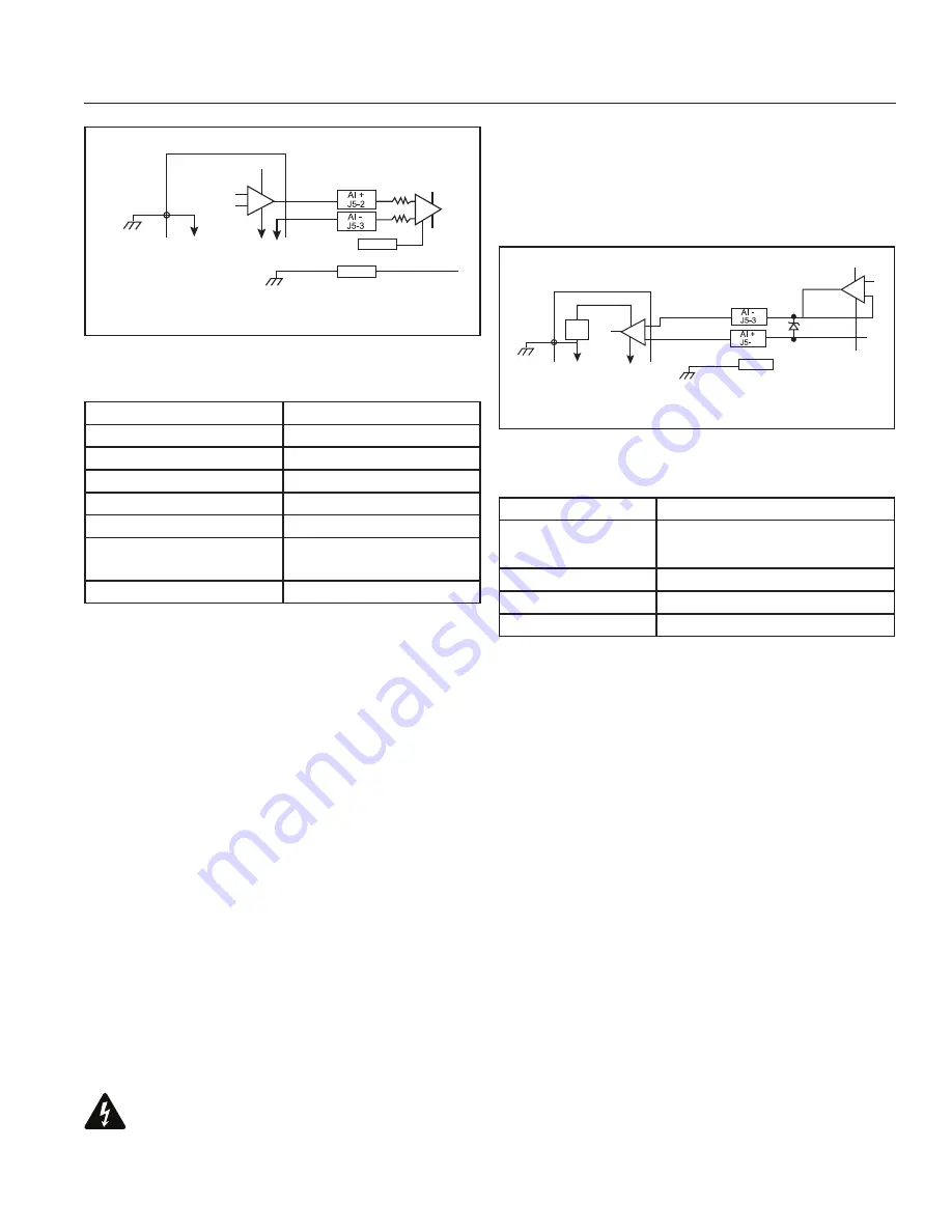
Figure 21
–
Analog Output Wiring from External Controller
Analog Output Specifications
Description
Specification
Absolute Max Voltage * -5 V to 15 V on Analog Out +
±5 V on Analog Ref
± 5 V on Analog Ref
0-10 V
Load Resistance
2 kΩ or higher
Output resolution
11 bits
* Circuits are protected from switching transients. Sustained
voltage outside the Absolute Max range may damage the
circuit. These signals are intended for connection only to higher
impedance circuits.
4.12 COMMUNICATIONS
Serial communication to the actuator is provided through the
8 mm communication connector on the front of the actuator.
The serial interface is two wire multi-drop RS485 and is optically
isolated from all other circuits. The actuator supports Modbus
RTU protocol for access to all drive parameters as described
in the Tritex II Parameter Manual and Tritex II Modbus Protocol
Specification. Default settings for the port are: Baud Rate =
19,200, Even Parity, Modbus device ID address = 1.
The following picture and table show connector pin-outs. Refer
to the Termination Board diagrams in the I/O Connector Wiring
section for wiring to terminal block J5 under the access cover.
Though in most cases only the 485+ and 485- signals are
required, the 485 COM signal can enhance noise rejection
if wired back to the master device signal common. The
communications cable must be shielded with shield or shield
drain wire connected to connector pin 2 or the connector body
to meet EMC requirements.
+14V
Single Point
Panel
Ground
External Controller
Single Point
Panel
Ground
Ground on Power
Connector
GND
Vdc
+
-
4
IO Com
Transient
Suppressor
3k
Ω
Figure 20
–
Analog Input Wiring from External Controller
Analog Input Specifications
Description
Specification
Absolute Max Input Voltage * ±40 Vdc to I/O Common
Differential Voltage Range
-10 V to +10 V
Analog In + Voltage Range
-15 V to +15 V
Analog In – Voltage Range
-15 V to +12 V
Input impedance
100 kΩ
Input resolution
13 bits over full -10 V to
+10 V range
Update rate
0.5 ms
* Inputs are protected from switching transients. Sustained
voltage outside the Absolute Max range may damage the
circuit.
4.11 ANALOG OUTPUT
A 0-10 V analog output is provided. With the 4-20 mA option,
the voltage output channel described here is replaced with a
4-20 mA channel described in a different section. The function
of this output is programmable. It can be used for position,
velocity, or current monitoring, and can be dynamically switched
between two sources.
The intent of this output is to provide a “monitor” type value not
a “control” value, meaning the performance is not intended for
the user to close a high-speed position loop around this signal.
The analog output signal is a voltage from the Analog OUT
terminal to the Analog REF terminal. The channel is not
isolated and Analog OUT is at the same voltage as the DC
Input (main power) terminal. The Analog Reference terminal
should only be used when connected to an isolated input or a
differential input.
DO NOT CONNECT TO A GROUNDED POINT
EXTERNALLY! A differential input should be used with this


