Exalt Installation and Management Guide
EX-i Series FDD Digital Microwave Radios
32
202675-005
2011-08-30
– In the GUI (
), the diplexer selection must match the type and
orientation of the diplexer installed.
If all other parameters are still configured at their factory default settings, the radios can now be
connected back-to-back to verify that the link is communicating and perform any other desired tests.
See
for test information.
describes each page of the GUI. Most configuration parameter settings are
intuitive. The following link parameters must match at both ends for the link to communicate:
•
Link Security Key (
•
Bandwidth (
)
•
RF Frequency (
), the channel plans match, but are opposite Tx and Rx
frequencies for a link.
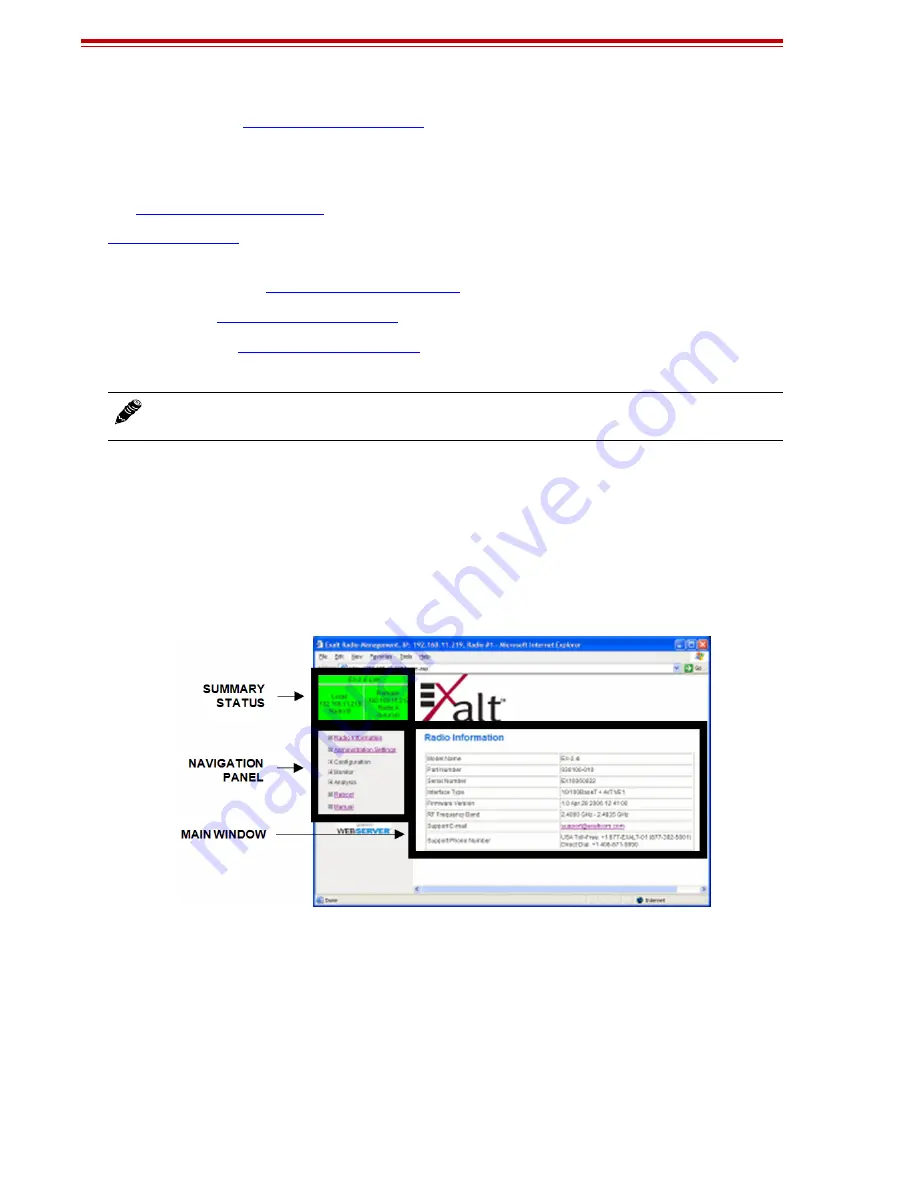
Navigating the GUI
The GUI provides the primary interface for all configuration and management. There are three sections
of the main GUI window:
•
Summary status information section (upper-left corner)
•
Navigation panel
•
Main window
Figure 20 Exalt GUI window description
Summary Status Section
This section of the Exalt GUI provides a review of the system status.
In the screens in Figure 21, the top bar illustrates the alarm condition of the link. The information
inside the bar is equivalent to the entry of the Link Name set by the administrator in the Administration
Settings page.
The color of the panel indicates alarm status:
Note:
Changing any of these parameters causes a temporary loss of link. The GUI displays a
warning and provides an opportunity to cancel changes.
Summary of Contents for EX i GigE Series
Page 133: ...202675 005 2011 08 30...


