5 Commissioning
5/4
5.8.1.1 Standard TIG torch
•
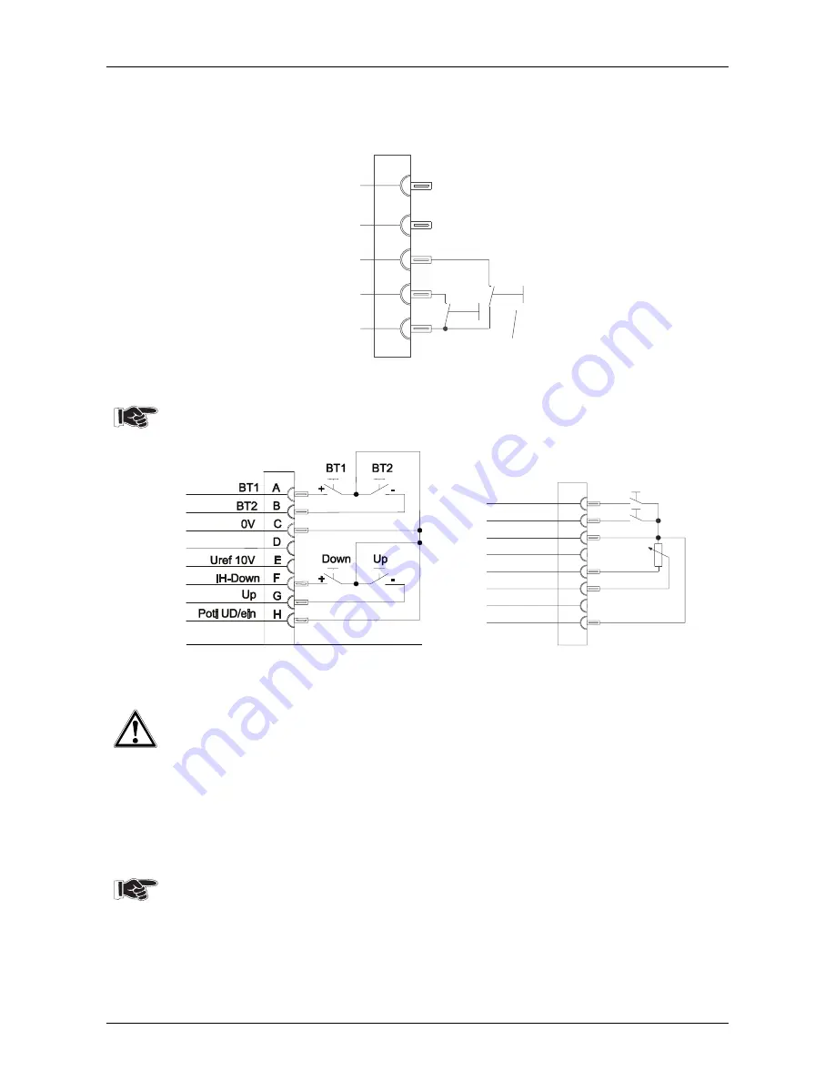
Insert the torch control lead plug (5-pole) into the connection socket (A1) and lock.
The welding machines are supplied as standard with torch trigger pin assignment B1 and gas
connection G1/4".
5
4
3
2
1
BT
I1
I2
Fig. 5/5: Connection socket connection B1
5.8.1.2 TIG Up/Down or TIG potentiometer welding torch
Potentiometer torches available on the market e.g. from Binzel can be used.
•
Insert the torch control lead plug (8-pole) into the connection socket (B1) and lock.
Fig. 5/6 Connection socket assignments
Up/Down torch
Uref 10V
Uref 10V
IH-Down
Poti UD/ein
Poti UD/ein
Up
H
G
E
F
10k
0V
C
D
BT1
BT2
A
B
Fig. 5/7: Connection socket assignments
Potentiometer torch
5.8.2
Shielding gas supply (shielding gas cylinder to the welding machine)
No impurities must be allowed to enter the shielding gas supply as these could cause
blockages in the shielding gas supply.
•
Place shielding gas cylinder in the retainer provided for it and secure with chains.
•
Before connecting the pressure reducer to the gas cylinder, open the cylinder valve briefly to
blow out any dirt present.
•
Screw the pressure reducer onto the cylinder valve, ensuring a gas-tight connection.
•
Connect the pressure reducer to the G¼ shielding gas connection (F1) on the rear of the
machine.
•
Open gas cylinder valve and set recommended gas quantity on the pressure reducer.
Rule of thumb for gas flow rate:
Diameter of gas nozzle in mm corresponds to gas flow in l/min.
Example: 7 mm gas nozzle corresponds to 7 l/min gas flow
5.8.3 Workpiece
lead
•
Insert cable plug of the workpiece lead into the welding current socket (C1
)
and lock by turning
to the right.
Summary of Contents for TRITON 260 DC
Page 57: ...10 Circuit diagram 10 1 10 1 TRITON 260 Circuit diagrams are also in the machine...
Page 58: ...10 Circuit diagram 10 2...
Page 59: ...10 Circuit diagram 10 3 10 2 TRITON 360 500 Circuit diagrams are also in the machine...
Page 60: ...10 Circuit diagram 10 4...
Page 61: ...10 Circuit diagram 10 5...


