5 Commissioning
5/2
5.4
Welding machine cooling system
To obtain an optimal duty cycle from the power components, the following precautions should be
observed:
•
Ensure that the working area is adequately ventilated,
•
Do not obstruct the air inlets and outlets of the machine,
•
Metal parts, dust or other foreign bodies must be kept out of the machine.
5.5 Workpiece
lead,
general
Remove paint, rust and dirt from clamping and welding areas with a wire brush! The
workpiece clamp must be mounted near the welding point and must be fixed in such a way
that it cannot come loose of its own accord.
Structural parts, pipes, rails etc. may not be used as return leads for the welding current
unless they are the workpiece themselves!
A perfect current connection must be ensured where welding benches and appliances are
concerned!
5.6 Connection
groups
If welding is performed alternately by different methods, e.g. TIG, MIG/MAG or MMA and if
one or two welding torches and an electrode holder are connected to the machine, the
open-circuit/welding voltage is applied simultaneously to both!
Therefore, always place the torch and the electrode holder on an insulated surface before
starting work and during breaks.
A1
D1
E1
F1
B1
C1
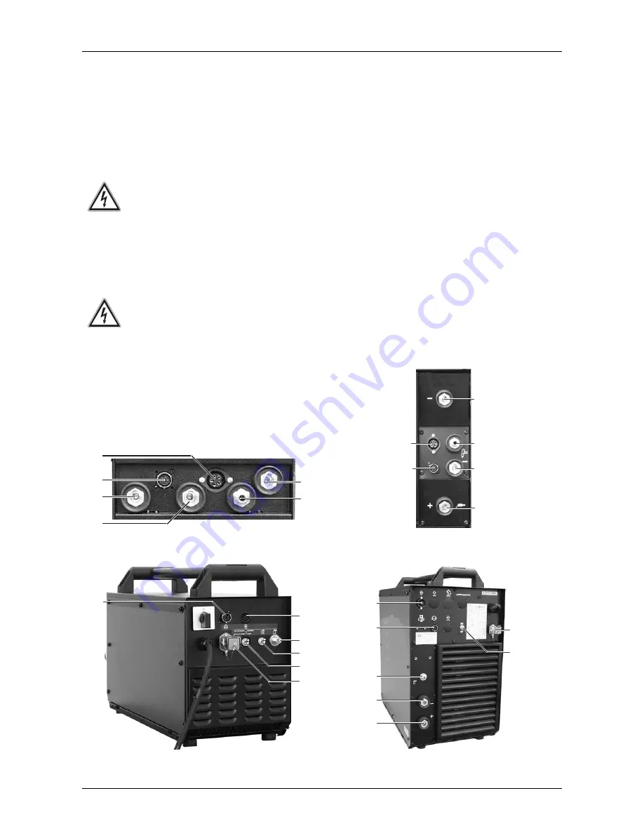
Fig. 5/1 Group of connections on the front of the
machine TRITON 260
A1
D1
E1
F1
B1
C1
Fig. 5/3 Group of connections on the front of the
machine TRITON 400/500
A2
G2
F2
E2
D2
C2
Fig. 5/2 Group of connections on the rear of the
machine TRITON 260
G2
A2
F2
I2
C2
E2
H2
Fig. 5/4 Group of connections on the rear of the
machine TRITON 400/500
Summary of Contents for TRITON 260 DC
Page 57: ...10 Circuit diagram 10 1 10 1 TRITON 260 Circuit diagrams are also in the machine...
Page 58: ...10 Circuit diagram 10 2...
Page 59: ...10 Circuit diagram 10 3 10 2 TRITON 360 500 Circuit diagrams are also in the machine...
Page 60: ...10 Circuit diagram 10 4...
Page 61: ...10 Circuit diagram 10 5...


