background image

Aquafilter 


E9_Next_Ing_rev03 – 10/10/2018 

  12 

E9 NEXT 


CHAPTER 4 


4.1 

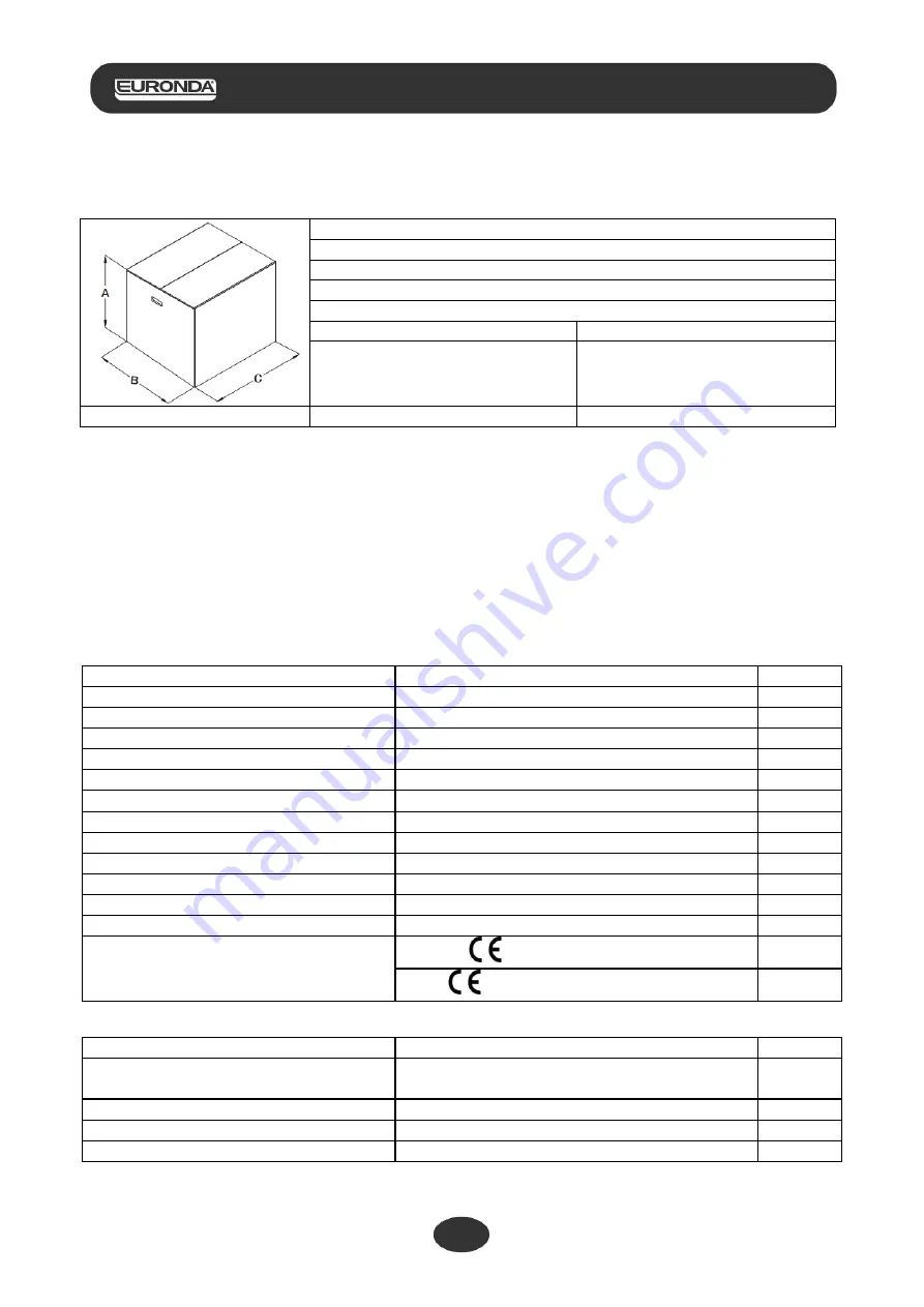
WEIGHT AND DIMENSIONS OF PACKAGING 


Overall dimensions of packaging:


A = 545 mm 
B = 560 mm 
C = 745 mm 

Total weight of packaging: 

E9 NEXT 18L 

E9 NEXT 24L 

50 kg 

54 kg 

Fig. 4.1-1 


4.2 

RECEIPT AND HANDLING 

On receipt of the machine, check that the packaging is intact (keep it for future despatches). 
Open the packaging and check that: 
-  the supply meets the technical specifications (chap. 4.3 “Description of contents”); 
-  there are no obvious signs of damage. 


If any damage or missing parts are discovered, inform the hauler, wholesaler or Euronda S.p.A immediately, 
providing all details. 
Handle the packed unit as described in chap. 6.1 “Work environment: positioning” (Fig. 6.1-1). 


4.3 

DESCRIPTION OF CONTENTS 

Description 

Specifications 

Quantity 

Steam sterilizer E9 NEXT 

Steriliser 18L - Steriliser 24L 

Tray 

Anodized aluminium perforated tray 

Tray carrier  

Support with 5 compartments in stainless steel 

Extractor pincer  

Pincers for extracting trays  

Door adjustment lever  

Stainless steel lever for adjusting the door gasket 

Water drainage tube 

Transparent PVC tube with quick fit attachment 

Overfill draining tube 

Transparent PVC tube 

Instructions manual 

This manual 

Warranty certificate 


Quick start sheet 


Installation sheet 


Test Report 


Declaration of conformity 

Steriliser: 

 0051


Boiler:


 0497 


4.3.1  Optional devices (also see Appendix 10) 
Description 

Specifications 

Quantity 

Aquafilter 

External  deioniser  for  the  automatic  supply  of 
water 

Integrated printer 

Thermal paper printer 

Integrated printer 

Label Printer 

External printer 

Label Printer 


Summary of Contents for E9 Next 18L

Page 1: ...Instructions manual 0051 E9 Next...

Page 2: ...Our devices comply with all the applicable safety regulations in force and present no danger to the operator when used according to the instructions Please also note that Euronda S p A declines all l...

Page 3: ...ee Appendix 10 12 CHAPTER 5 13 5 1 DESCRIPTION OF UNIT 13 5 1 1 Front elements 13 5 1 2 Rear elements 13 5 1 3 Upper elements 14 5 2 OVERALL SPACE REQUIRED 15 5 3 TECHNICAL DATA AND NOISE 16 5 3 1 Rat...

Page 4: ...he load through the identification of the user 45 7 7 9 Ethernet connection set up 46 7 7 10 Planning set up 47 7 9 LONG PERIODS OF INACTIVITY 49 CHAPTER 8 50 8 1 E MEMORY SOFTWARE 50 8 1 1 Minimum sy...

Page 5: ...EXT APPENDIX 5 69 Description of programs 69 APPENDIX 6 71 Description of Tests 71 APPENDIX 7 74 Validating the cycles 74 APPENDIX 8 75 Quality of process water 75 APPENDIX 9 76 Troubleshooting 76 APP...

Page 6: ...ase of dispute the date indicated on the purchase invoice showing the serial number of the unit will be considered as valid NOTE 1 please retain the original packaging and use it each time the unit ne...

Page 7: ...roup responsible for the use and routine maintenance of the unit and for operator training The responsible authority is legally responsible for the installation operation and use of the unit 2 3 USING...

Page 8: ...ORMATION This symbol is used to draw the reader s attention to particularly important notions for operator safety INFORMATION AND PRECAUTIONS This symbol refers to general indications and advice STRIC...

Page 9: ...er supply disconnect the mains supply If this is distant or not visible by the person carrying out the maintenance work turn the switch to OFF and secure it with a padlock or alternatively lock the el...

Page 10: ...cts main electrical power supply Protection of the electronic card against short circuit both the transformer and the entire low voltage circuit are self protected Disconnects one or more low voltage...

Page 11: ...ed instruments Control devices Description Effect Pressure levelling restores the system to its normal pressure values in the event of manual stops or alarms and or warnings during the cycle Automatic...

Page 12: ...r or in front of it as you may be scalded by the steam Fig 3 4 2 3 In case of blackout during a sterilization cycle every try to open the door is absolutely forbidden A potential residual pressure cou...

Page 13: ...Fig 6 1 1 4 3 DESCRIPTION OF CONTENTS Description Specifications Quantity Steam sterilizer E9 NEXT Steriliser 18L Steriliser 24L 1 Tray Anodized aluminium perforated tray 5 Tray carrier Support with 5...

Page 14: ...SD card slot the SD card which stores the machine cycle data is housed in this slot 5 Optional thermal printer cover see chap 5 4 Integrated printer Fig 5 1 1 1 Devices on the front of the unit with...

Page 15: ...ext_Ing_rev03 10 10 2018 14 E9 NEXT 5 1 3 Upper elements 1 Clean water tank 2 Dirty water tank 3 Filters 4 Max clean water and max dirty water sensor 5 Minimum clean water level conductivity meter sen...

Page 16: ...IRED Overall dimensions of the machine with door closed fig 5 2 1 E9 NEXT 18L E9 NEXT 24L L 460 mm H 455 mm D 615 mm Overall dimensions of the machine with door open fig 5 2 1 E9 NEXT 18L E9 NEXT 24L...

Page 17: ...erate Indoor use Altitude up to 2 000 m a s l Temperature 5 40 C Max relative humidity 85 Max variation in mains voltage 10 Installation category overvoltage category II Degree of pollution 2 Temporar...

Page 18: ...e information shown in the following figure is subject to change Fig 5 3 1 1 The label of the unit bears symbols the meaning of which is shown below SYMBOL DESCRIPTION SN SERIAL NUMBER The symbol must...

Page 19: ...le the printer shows the results of the cycle both if it was successful or unsuccessful or if it has been stopped manually or caused an alarm The printer only works if the label roll is inserted If no...

Page 20: ...roll if present 3 Fit the new paper roll as shown in the figure make sure the paper leaves the roll in the right direction 4 Pull out a small quantity of paper and close the cover 5 Tear off the exce...

Page 21: ...ing Fig 6 1 1 Open the top of the cardboard packaging Make sure there is no evident damage and that all the parts are present Use the relative belts to lift the unit two people required taking care to...

Page 22: ...Before installation make sure to remove the kit of accessories from inside the unit Install the unit so that the power lead does not kink or become squashed but has a free run to the socket The unit m...

Page 23: ...t Position the unit so that the plug is accessible Do not allow the lead to bend tightly and do not place any object on it Do not use extension cords Only use the original lead ONLY USE ORIGINAL SPARE...

Page 24: ...the ON OFF switch 6 5 HOW TO USE THE CONTROL PANEL 6 5 1 How to use the control panel The E9 NEXT steam steriliser features a touch screen user interface 1 of Fig 6 5 1 1 which integrated the control...

Page 25: ...he unit is switched on 6 7 TANKS INSTRUCTIONS FOR FILLING AND DRAINING The unit features two separate tanks one for the clean water required for the cycles and one for the used water that is collected...

Page 26: ...2 Fill the clean water tank with fresh clean water 1 di Fig 6 8 1 WARNING always use good quality clean water Appendix 8 Quality of process water To ensure correct machine operation it is fundamental...

Page 27: ...ning chap 3 4 Residual risks NEVER REUTILISE USED WATER Get hold of an empty tank fit the clear tube supplied with the unit after removing the discharge section cover 3 of Fig 6 8 2 to the connector w...

Page 28: ...ription of Programs Always observe the maximum load limit established and set by Euronda S p A for each solid material to sterilise The maximum sterilisable load of the unit is indicated in Annex 5 Th...

Page 29: ...N OFF button the following welcome screen appears After a few seconds this is replaced by the HOME screen If no activity is performed on the autoclave for a minute the home screen is replaced by the b...

Page 30: ...e inside the unit In order to load the material to sterilize correctly carefully read all the instructions given in Appendix 1 Preparing the instruments for sterilization Appendix 2 Packaging and Appe...

Page 31: ...d 1 5 2 kg in this case next to the zig zag line the number of pre vacuum cycles for removing the air required by the cycle 3 in this case next to the flat line the sterilisation time 4 minutes in thi...

Page 32: ...with an approximate estimate of the time left to the end of the cycle and the padlock symbol to indicate that the door is locked At the bottom the hand icon for manually stopping the cycle and the i i...

Page 33: ...ER OF BURNS When the unit finishes the sterilization cycle and the door is opened to remove the sterilized instruments the inner parts of the boiler and door are still very hot These must not be touch...

Page 34: ...ly be opened after giving consent by touching the screen see 7 6 CAUTION LOAD NOT STERILE HANDLE WITH CARE 7 2 2 Information on process parameters Additional information on the parameters of the curre...

Page 35: ...eceive the password and unlock the Personal Light and Light Stock cycles register your E9 Next at www myeuronda com ATTENTION these sterilization programs can be used only for solid loads They cannot...

Page 36: ...d in Appendix 6 Description of tests Select the TEST icon to return to the test cycle menu From this screen the steriliser test cycles can be run by touching the corresponding icons 1 pressure gauge i...

Page 37: ...heating see Appendix 6 It will no longer be possible to perform the test If the unit is pre heating and you switch it off and then switch it back on again it still will not be possible to perform the...

Page 38: ...en and then the RED HAND button in the next screen This procedure applies to all sterilisation and test cycles At this point the steriliser will start a sequence of operations allowing the steam to be...

Page 39: ...to release it 7 5 POWER BLACKOUTS Power cuts may occur during the operation of the unit caused by the electricity provider In this case the E 02 alarm message appears see Appendix 9 Troubleshooting 7...

Page 40: ...ls to print to 0 In order to change the number of labels simply select touch the upper field and change the value using the up and down arrows Use the lower field to change the expiry days The various...

Page 41: ...Aquafilter E9_Next_Ing_rev03 10 10 2018 40 E9 NEXT When the cycle is launched the user will be able to select the user name on the list of generic users OPERATOR 1 OPERATOR 2 etc...

Page 42: ...hanged at a later stage To change the password enter the Users menu select the user whose password must be changed and select the password field A new screen will appear where it will be sufficient to...

Page 43: ...ally connecting the desired printer for interfacing it with the autoclave proceed as follows The following printer selection options are available 1 integrated thermal printer 2 integrated label print...

Page 44: ...possibility of reprinting the labels The cycle will complete normally without printing the labels In this case enter the settings menu and touch the Last Print Cycle icon Then set the number of labels...

Page 45: ...led on the autoclave This is a device giving the possibility of automatically obtaining the water required for the operation of the steriliser through direct connection to the water mains After comple...

Page 46: ...fication function is activated While this function is active when the door is opened at the end of the cycle if the load is sterile the autoclave asks users to identify themselves by selecting their n...

Page 47: ...3 10 10 2018 46 E9 NEXT 7 7 9 Ethernet connection set up To activate the autoclave Ethernet connection proceed as shown in the figure The default IP address is 192 168 0 75 This can be changed for ada...

Page 48: ...losed and the water level above the minimum On the set day and time the autoclave automatically starts the planned cycle and or test The following combinations are possible Vacuum Test Bowie Dick Heli...

Page 49: ...Aquafilter E9_Next_Ing_rev03 10 10 2018 48 E9 NEXT...

Page 50: ...lave is switched on the user is reminded to execute the required test To activate this function proceed as indicated in the figure 7 9 LONG PERIODS OF INACTIVITY 1 Disconnect the unit from the mains s...

Page 51: ...start automatically If this does not happen proceed as follows a click on Start and select Run b type D setup setup exe where D is the CD ROM drive and click on Next to run the installation programme...

Page 52: ...bar 3 work area 1 Task bar This is divided into four sections File this is the E Memory Software home page which manages the device cycles Link this screen shows the status of the device connected to...

Page 53: ...use the Filter option to make selective cycle searches by result date type cycle number or device serial number To select multiple cycles hold down CTRL or SHIFT CTRL to select cycles one by one or SH...

Page 54: ...creen delete the external memory or modify the password When entering the password you are asked to confirm it by typing it in again The predefined password is certificate 5 Default e mail you may ent...

Page 55: ...slot simply push it in ensuring that the pin faces the front of the autoclave until it clicks in position If the SD card enters the slot with difficulty do not force the mechanism and check it was ins...

Page 56: ...ccelerate acquisition e g if the SD memory card contains many cycles click on this button The function is automatically disabled following acquisition Safe removal of the SD memory card to remove the...

Page 57: ...must be correctly used serviced and checked at regular intervals These precautions will ensure continuous safe and efficient use of the unit To prevent operator hazards the unit must be subject to reg...

Page 58: ...moved the tray support using a non abrasive damp cloth To dampen the cloth use only and exclusively distilled or demineralised water Follow the same procedure for cleaning the trays and their support...

Page 59: ...e unit with direct sprays or high pressure jets or water since any infiltration into the electrical components could prejudice the working of the machine and the safety systems Emptying and cleaning t...

Page 60: ...sponge supplied and water Use the soft side of the sponge not the abrasive side Clean with care paying particular attention to any dirt that may have deposited in the corners 6 Remove the filters of t...

Page 61: ...valve CAUTION HIGH TEMPERATURE Only perform this operation when the machine is cold CAUTION DISCONNECT THE POWER SUPPLY BEFORE STARTING WORK Non observance may cause serious injury to people or may se...

Page 62: ...therefore jeopardise the result of the cycle Proceed as follows 1 Open the door Always work with the unit cold 2 Fit the supplied adjustment lever Fig 9 2 2 1 into the slot under the door Fig 9 2 2 2...

Page 63: ...of Fig 5 1 1 2 by turning it anticlockwise Screw on the new filter by turning it clockwise until it is tight Replacing the door seal Grip the lip of the seal with two fingers and remove it Clean the s...

Page 64: ...e formation of rust in the steriliser is the use of water containing chlorine such as drinking water sea water or water containing disinfectants or detergents Only use good quality distilled water CAU...

Page 65: ...te The user must therefore send or instruct other people to send the unit to one of the sorted waste collection centres set up by the local councils or send it to the dealer against the purchase of an...

Page 66: ...g personnel Decontamination is carried out using detergents and generally solutions that are active against HIV HBV and HCV or by washing at 93 C for ten minutes in thermo disinfectors Observe the ind...

Page 67: ...e a space of at least 30 mm between the instrument and the welding strip 3 The instruments must be positioned so that they can be extracted by their handle 4 The sealing strip on the pouch must be con...

Page 68: ...ing may compromise the quality of the sterilisation Mirrors should be placed glass side down Do not stack the trays on top of each other always use the tray supports It is necessary to leave a space b...

Page 69: ...ur the dispersion of heat Wait for the material to drop to room temperature before stocking it before stocking make sure that the packages are intact and check the chemical colour change if the packag...

Page 70: ...plateau period 4 18 20 3 5 18 Drying time Auto 15 15 15 5 Maximum load solid porous 4 5 1 5 kg 6 2 kg 4 5 1 5 kg 6 2 kg 4 5 1 5 kg 6 2 kg 0 6 0 2 kg 0 6 0 2 kg The cycle profile may vary from one sof...

Page 71: ...ches products that will have to be kept sterile for a long period of time The length of this cycle depends on the weight of the load on the type of load and on the temperature in the chamber upon star...

Page 72: ...ength of sterilization phase plateau period 3 30 3 30 Drying time Total time 21 32 26 30 26 33 Vacuum test The sole purpose of the diagram is to illustrate the quality performance of the cycle This te...

Page 73: ...fficiency of the preliminary vacuum and the penetration of steam within the cavities the temperature and pressure values of the saturated steam during the sterilization phase The packet for the B D te...

Page 74: ...ads in particular the efficiency of the preliminary vacuum and the penetration of steam within the cavities the temperature and pressure values of the saturated steam during the sterilization phase Af...

Page 75: ...stics that may hinder the penetration of steam in an equal or greater amount than those of a hollow load Porous load material that is capable of absorbing fluids in particular this regards A a full po...

Page 76: ...er Condensate Dry residue 10 mg l 1 mg l Silicon oxide 1 mg l 0 1 mg l Iron 0 2 mg l 0 1 mg l Cadmium 0 005 mg l 0 005 mg l Lead 0 05 mg l 0 05 mg l Heavy metal residues 0 1 mg l 0 1 mg l Chlorides 2...

Page 77: ...op the cycle and therefore the load is not sterile The screen shows the name of the cycle at the top and the relative error code at the bottom in this case and the door locked icon padlock If this scr...

Page 78: ...load in the boiler just one tray If the problem persists contact the assistance service E21 Excessive pressure during sterilisation Fault during the sterilization phase Allow the steriliser to cool a...

Page 79: ...ical filter at the front of the machine is not clogged E31 Minimum vacuum not reached during the vacuum test Hydraulic leak during vacuum phase Allow the steriliser to cool and then perform a vacuum t...

Page 80: ...ew hours then perform a sterilisation system If the problem persists contact the assistance service E56 Temperature of lower band too high Fault in the electronic board or temperature sensor Switch of...

Page 81: ...CODE DESCRIPTION SOLUTION Used water at maximum level Empty the used water tank Clean water under minimum level Fill the clean water tank with distilled or deionized water W41 An attempt was made to s...

Page 82: ...et back in by pushing the pin toward the steriliser W80 Lower band heater temperature not suitable for cycle start Resistance fault W81 Upper band heater temperature not suitable for cycle start Resis...

Page 83: ...folder and click twice on setup The data in the SD memory card is not acquired by the E Memory Software Check PC and SD memory card communication in the connections page The E Memory Software does no...

Page 84: ...ng the resins will appear on the display of the E9 NEXT steriliser The quality of the water produced is also indicated by a led on the deionizer as well as the message on the display of the unit there...

Page 85: ...evice that on completion of each cycle gives the possibility of expressing the result of such cycle both if it is successful or unsuccessful or if it has been stopped manually or caused an alarm This...

Page 86: ...aper roll integrated printer The thermal paper roll printer is a device that on completion of each cycle gives the possibility of expressing the result of such cycle both if it is successful or unsucc...

Page 87: ...he possibility of expressing the result of such cycle both if it is successful or unsuccessful or if it has been stopped manually or caused an alarm This thermal impact printer gives the possibility o...

Page 88: ...9_Inspection_Recorder_Eng_rev00 26 08 11 EURONDA S p A Via dell Artigianato 7 36030 Montecchio Precalcino VI ITALY Tel 39 0445 329811 Fax 39 0445 865246 Internet www euronda com E mail info euronda co...

Reviews: