background image

43 


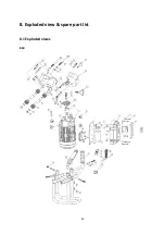
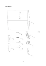
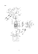
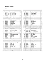
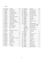
8.2 Spare part lists 

 
B60 
 

No.  Part number 

Description 

Qty 


No. 

Part number 

Description 

Qty 

B60.0022 

Protective handle 


34 

B60.1006 

Guide plate assembly: 

030E.0091/Y2 

On / off switch 220V 


34A 

B60.0037 

Left semicircle slider 

030E.0092/Y2 

On / off switch 110V 


34B 

B60.0038 

Right semicircle slider 

B60.0018A 

Green signal light 


34C 

B60.0039 

Lower plate 

B60.0016 

Inner six angle bolt 


34D 

B60.0040 

Upper plate 

020.0217 

Spring washer 


34E 

020.0223 

Screw 

B60.1008B 

Electrical box assembly 


35 

B60.0041 

Screw M10 

020.0101 

Panel screw BKVZ M4 x 8 


36 

B60.0030 

Elastic washer 

B60.0035 

Cylindrical pin φ5 


37 

B60.0042 

Flat washer M10 

B60.0066 

Capacitance 


38 

B60.0044 

Steel sleeve 

10 

B60.0067 

Capacitor holder 


39 

B60.0043 

Contact roller 

11 

B60.0068 

Screw M5 x 8 


40 

B60.0045 

T-Nut 

12 

B60.0007B 

Cooling plate 


41-43 

020.0037 

Cable clamp complete 

13 

B60.0004 

Rubber isolator 


44 

020.0031 

Coupling nut PG11 (main cable) 

14 

020.0329 

Screw M4 x 16 


45 

020.0036 

Main cable complete 220-240V 

15 

B60.0008 

Rubber cord protector 


020.0036/AU 

Main cable Australia 


16 

B60.0054 

Motor cable end cover 


020.0036/UK 

Main cable UK 220V 


17 

B60.1001B 

Motor assembly 


020.0036/UK 
110-16A 

Main cable UK 110V 16A 


18 

B60.0002 

Key 


020.0036/USA 

Main Cable USA 


19 

B60.0026 

Cutter head connecting sleeve 


46 

B60.0062 

Inner hex bolt 

20 

B60.0027 

Cutter body 


47 

B60.1003 

Frame 

21 

LKS.15 

Cutting plate 

10 


48 

B60.1004 

Handle bar U-shaped 

22 

B60.0029 

Screw  

10 


49 

B60.0063 

Inner hex bolt 

23 

B60.0030 

Elastic washer 


50 

B60.0014 

Duckbill gasket 

24 

B60.0031 

Screw  


100 

CAS.B60 

Metal case 

25 

B60.0032 

Adjusting knob 


101 

SAF.100 

Safety goggles 

26 

B60.1009 

Cutter head cover with Logo tag 


102 

SAF.300 

Protective gloves 

27 

B60.0034 

Pointer plate 


103 

SAF.200 

Ear plugs 

28 

020.0305 

Washer M8 


104 

B60.0049 

Spanner Torx T20 

29 

100.0031 

Spring washer 


105 

IMB.US4 

Allen key 4.0 mm 

30 

B60.0036 

Adjustable handle 


106 

IMB.US6 

Allen key 6.0 mm 

31 

B60.0046 

Screw 


107 

IMB.US8 

Allen key 8.0 mm 

32 

B60.0056 

Spring washer 


109 

B60.0050 

Open spanner 18mm 

33 

B60.0055 

Leveling pad 


110 

B60.0051 

Open spanner 32mm 


Summary of Contents for B60

Page 1: ...rial number Date of purchase Don t forget to register your machine at www euroboor com register only when registered you benefit from extended warranty Bevelling machine B60 B60S Operators manual V 1 0 EN ...

Page 2: ...2 ...

Page 3: ...p you be more productive Before operating your bevelling machine please read all instructions first These include the Operators Manual and warning label on the unit itself With proper use car and maintenance your model will provide you with years of effective bevelling performance TO REDUCE THE RISK OF INJURY USER MUST READ AND UNDERSTAND ALL INSTRUCTIONS EUROBOOR BV Kryptonstraat 110 2718TD Zoete...

Page 4: ...4 ...

Page 5: ...g blade 19 3 4 Replacing milling head 21 3 4 1 Disassembly milling head cover 21 3 4 2 Removing and reinstalling milling head 21 3 5 Setting bevel angle 22 3 6 Setting bevel depth width 23 3 7 Conversion for use on pipe 25 4 Using the machine 27 4 1 Switching machine into standby mode 27 4 2 Switching motor on and off 27 4 3 Speed adjustment 28 4 4 Overload protection 28 5 Working with operating t...

Page 6: ...ep bystanders children and visitors away while operating a power tool Distractions can cause you to lose control ELECTRICAL SAFETY 1 Power tool plugs must match the outlet Never modify the plug in any way Do not us any adapter plugs with earthed grounded power tools Unmodified plugs and matching outlets will reduced risk of electric shock 2 Avoid body contact with grounded surfaces such as pipes r...

Page 7: ...ect power tool for your application The correct power tool will do the job better and safer at the rate for which it was designed 2 Do not use the power tool if the switch does not turn it on or off Any tool that cannot be controlled with the switch is dangerous and must be repaired 3 Disconnect the plug from the power source and or the battery pack from the power tool before making any adjustment...

Page 8: ...ave a sufficient cross section so as to prevent an excessive drop in voltage or overheating An excessive drop in voltage reduces the output an can lead to failure of the motor d Never use multiple extensions cables together Use a single longer one instead e Check the plug cable and machine for damage each time using the machine f Remove the plug from the plug socket before undertaking an maintenan...

Page 9: ...abels and identification plates as they carry important information If unreadable or missing obtain replacement 3 TOOL USE AND CARE WARNING a Hold power tool by insulated gripping surfaces because the cutter may contact its own cord Cutting a live wire may make exposed metal parts of the power tool live and shock the operator WARNING b Use clamps or another practical way to secure and support the ...

Page 10: ... cutter inserts cutting plates to achieve quick and easy bevelling WARNING The machine should not be converted or modified e g for any other form of use other than as specified in these operating instructions Warranty will be voided and the user shall be liable for damages and accidents due to incorrect use 2 2 Description and features 1 Milling head cover 2 Guide plate assembly 3 Guide rollers 4 ...

Page 11: ...11 B60 B60S B60S shown image 1 1 image 1 2 ...

Page 12: ...12 B60 image 1 3 B60S image 1 4 ...

Page 13: ...umber is also mention on the machine case once on a sticker on the motor housing Additional serial number stickers are provided with the machine for your administration The serial number will help you and your sales point validate and identify the machine As example B6018110001 breaks down to B60 18 11 0001 Machine series Year of manufacture Month of manufacture Identification number Maintain labe...

Page 14: ... 8 Tooling Integrated milling head with 10 square inserts LKS 15 Power source 220 240V 50 60Hz 110 120V 60Hz B60S Weight nett machine 24 1 kg 53 lbs Weight gross incl case acc 34 0 kg 75 lbs Motor power 1800W 16 4 A Spindle speed 1675 2850 min 1 Edge angle 0 60 Maximum bevel width 24 mm 15 16 Pipe application Ø OD 150 600 mm 5 15 16 23 5 8 Tooling Integrated milling head with 10 square inserts LKS...

Page 15: ...an conformity symbol Confirms the conformity of the power tool with the directives of the European Community Class of protection I Product with basic insulation and exposed touchable conductive parts additionally connected to the protective earth conductor mm Millimeter Unit of measure for length width height or depth kg Kilogram Unit of measure for the mass V Volt Unit of measure for the electric...

Page 16: ...s and packaging allows materials to be recycled and used again Re use of recycled materials helps prevent environmental pollution and reduces the demand for raw materials Local regulations may provide for separate collection of electrical products from the household at municipal waste sites or by the retailer when you purchase a new product ...

Page 17: ...hine Supervision is required when inexperienced operators use this machine ELECTRICAL SAFETY The machine electronics have been designed for one voltage only Always check that the power supply corresponds to the voltage on the rating plate EUROBOOR B60 S is designed in class I grounded according to standard EN 61029 1 Earth grounding is required If the power supply cord is damaged it must be replac...

Page 18: ...ng corners show signs of wear as to make maximum use of the unused edge corners Replacing the cutting blades if they are completely worn out or no longer suitable for the operating task at hand All 10 blades need to be replaced at the same time Following steps cover all above mentioned handlings 3 3 1 Disassembly milling head cover To access the milling head it is advised to disassemble the millin...

Page 19: ...es multiple purposes a When repositioning or replacing the cutting blades it should be prevented that dirt gets in the way of proper installation b A clean milling head increases the life of the cutting blades 4 Reposition or replace the cutting blades as desired in exact reverse order The set screws should not be overtightened Make sure to remove all tools WARNING Shortly after operating the mach...

Page 20: ...20 image 2 3 ...

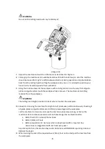
Page 21: ...r spindle If the milling head does not come off easily by hand use a pulley puller 4 For reinstallation clean all parts first and follow above steps in reverse order Make sure all parts are positioned correctly and that the securing bolt is not overtightened Make sure to remove all tools image 2 4 WARNING Shortly after operating the machine the milling head and cutting plates can be hot The cuttin...

Page 22: ...ver It is not necessary to loosen the bolts completely 2 Rotate the guide plate assembly in such a way that the indicator stripe on the guide plate assembly lines up with the desired amount of degrees 3 Tighten both angle adjustment lock bolts a little bit double check if the angle adjustment is still set to the desired amount of degrees and tighten the bolts completely Be careful not to overtight...

Page 23: ...BOOR B60 S has a wide bevel depth width adjustment range up to 24 mm bevel width at 45 degree angle Maximum bevel depth and width are different per bevel angle Below you will find measurements for most common bevel angle settings image 2 6 ...

Page 24: ...ection for bigger bevel width or Rotate the depth adjustment knob in clockwise direction for smaller bevel width 3 Tighten the depth adjustment lock handle image 2 7 Note The depth adjustment scale provides an indication of adjustment but is specified for 45 degree angle Always check the setting by using the machine on a piece of scrap metal and fine tune the setting when needed ...

Page 25: ...the machine which is done in the following steps 1 Loosen and remove both angle adjustment lock bolts with supplied 6 mm Allen key One can be found at either side of the milling head cover 2 Pull the complete guide plate assembly from the machine 3 Rotate the guide plate assembly 180 degree 4 Reposition the guide plate assembly 5 Fit and tighten both angle adjustment lock bolts B60S shown image 2 ...

Page 26: ...olt from the hole while holding the guide roller set 9 Fit the rectangular slide nut in the sliding slot 10 Reassemble the guide roller set on the bolt 11 Fit the bolt to the rectangular slide nut and tighten the bolt Be careful not to overtighten the bolt Original set up for use on plate New set up for use on pipe image 2 9 image 2 10 ...

Page 27: ...ding the motor If this is done with the motor still running the motor will not automatically restart when the standby on off switch is toggled from position 0 to position I again 4 2 Switching motor on and off B60 To switch on the motor press I on the motor on off switch When the motor runs the motor check indicator light green is burning To switch off the motor press 0 on the motor on off switch ...

Page 28: ... check the appropriate speed for the material you are working with and try a few settings on a test piece before starting with the actual operation 4 4 Overload protection B60s only EUROBOOR B60S is equipped with overload protection Overload can be caused by either to fast feeding rate or to deep bevel setting When the overload indicator light red is flickering the machine is being used at maximum...

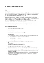
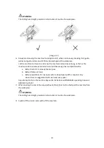
Page 29: ...ce 5 1 Bevelling plate material 1 Prepare the machine as described in chapter 3 Angle adjustment Angle adjustment should be between 1 and 60 degrees Depth adjustment It is strongly advised to have the depth adjustment not deeper than additional 6 mm per pass For example if you want to create a bevel width of 15 mm First setting 6 mm Second setting 12 mm Third setting 15 mm 2 Position the machine v...

Page 30: ...smooth bevel edge has multiple benefits a Better finish if it is already the last pass b Better lifetime of tools c Better preparation for next pass when a deep bevel width is required Any unevenness is exaggerated with each and every pass Any attempt to force the machine beyond its limitations will INCREASE operating time and REDUCE the finish 7 When nearing the end of the required bevel firmly b...

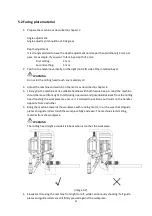
Page 31: ...mly grip the machine at its available handles with both hands Keep in mind the machine should be moved from right to left during operation and potential kick back from the milling head touching the workpiece may occur It is advised to position your hands on the handles opposite from eachother 5 Bring the machine towards the workpiece with running motor in such a way that all guide plates and guide...

Page 32: ...aration for next pass when a deep bevel width is required Any unevenness is exaggerated with each and every pass Any attempt to force the machine beyond its limitations will INCREASE operating time and REDUCE the finish 7 When nearing the end of the required bevel firmly but not too fast pull the machine from the workpiece WARNING The milling head might provide kick back when it touches the workpi...

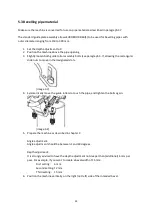
Page 33: ...7 allowing the rectangular slide nuts to move in the designated slots image 3 3 4 Symmetrically move the guide rollers to touch the pipe and tighten the bolts again image 3 4 5 Prepare the machine as described in chapter 3 Angle adjustment Angle adjustment should be between 1 and 60 degrees Depth adjustment It is strongly advised to have the depth adjustment not deeper than additional 6 mm per pas...

Page 34: ... from the workpiece WARNING The milling head might provide kick back when it touches the workpiece 10 Slowly start moving the machine from right to left clockwise while continuously checking if all guide plates and guide rollers are still firmly pressed against the workpiece Let the machine do its work and move the machine evenly slowly along as fast as the machine is able to remove material A smo...

Page 35: ...35 WARNING The milling head might provide kick back when it touches the workpiece 12 Switch off the motor and switch off the machine ...

Page 36: ... with bare hands Blow dirt and dust out of the motor housing with compressed air as often as dirt is seen collecting in and around the air vents Wear approved eye protection and an approved dust mask Never use solvents or other harsh chemicals for cleaning the non metallic parts of the tool These chemicals may weaken the materials used in these parts Use a cloth dampened only with water and mild s...

Page 37: ... without prior notice WARNING Since accessories other than those offered by EUROBOOR have not been tested with this product use of such accessories with this tool could be hazardous To reduce the risk of injury only EUROBOOR recommended accessories should be used with this product Consult your dealer for further information on the appropriate accessories ...

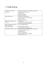
Page 38: ...ctive control unit Motor running roughly and or seizing up Bent spindle Shaft extending from the motor is bent Damaged or obstructed milling ehad Motor humming big sparks and motor has no force Motor damaged burned Frame under voltage Damaged defective wiring Machine highly contaminated dirty Fuse blows when motor is started Machine not connected to appropriate power supply Damaged or defective wi...

Page 39: ...39 8 Exploded view spare part list 8 1 Exploded views B60 ...

Page 40: ...40 B60 CONTINUED ...

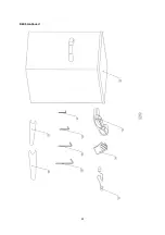
Page 41: ...41 B60S ...

Page 42: ...42 B60S continued ...

Page 43: ...M4 x 16 4 45 020 0036 Main cable complete 220 240V 1 15 B60 0008 Rubber cord protector 1 020 0036 AU Main cable Australia 16 B60 0054 Motor cable end cover 1 020 0036 UK Main cable UK 220V 17 B60 1001B Motor assembly 1 020 0036 UK 110 16A Main cable UK 110V 16A 18 B60 0002 Key 1 020 0036 USA Main Cable USA 19 B60 0026 Cutter head connecting sleeve 1 46 B60 0062 Inner hex bolt 2 20 B60 0027 Cutter ...

Page 44: ...Coupling nut PG11 main cable 1 15 B60 0008 Rubber cord protector 1 45 020 0036 Main cable complete 220 240V 1 16 B60 0054 Motor cable end cover 1 020 0036 AU Main cable Australia 17 B60 1001 Motor assembly 1 020 0036 UK Main cable UK 220V 18 B60 0002 Key 1 020 0036 UK 110 16A Main cable UK 110V 16A 19 B60 0026 Cutter head connecting sleeve 1 020 0036 USA Main Cable USA 20 B60 0027 Cutter body 1 46...

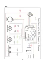
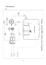
Page 45: ...45 8 3 Wiring diagrams B60 ...

Page 46: ...46 B60S ...

Page 47: ...__________________________ _______________________________________________________________________________ _______________________________________________________________________________ _______________________________________________________________________________ _______________________________________________________________________________ _____________________________________________________...

Page 48: ...48 ...
Reviews: