background image

31

Once the correct zone is displayed, press


F1


on the keyboard in 

order to activate a return to the station. This operation records the 

new work zone for the robot.

Press ON and close the hood.


The robot will go to charge and will 

start in this zone once the battery is fully charged.
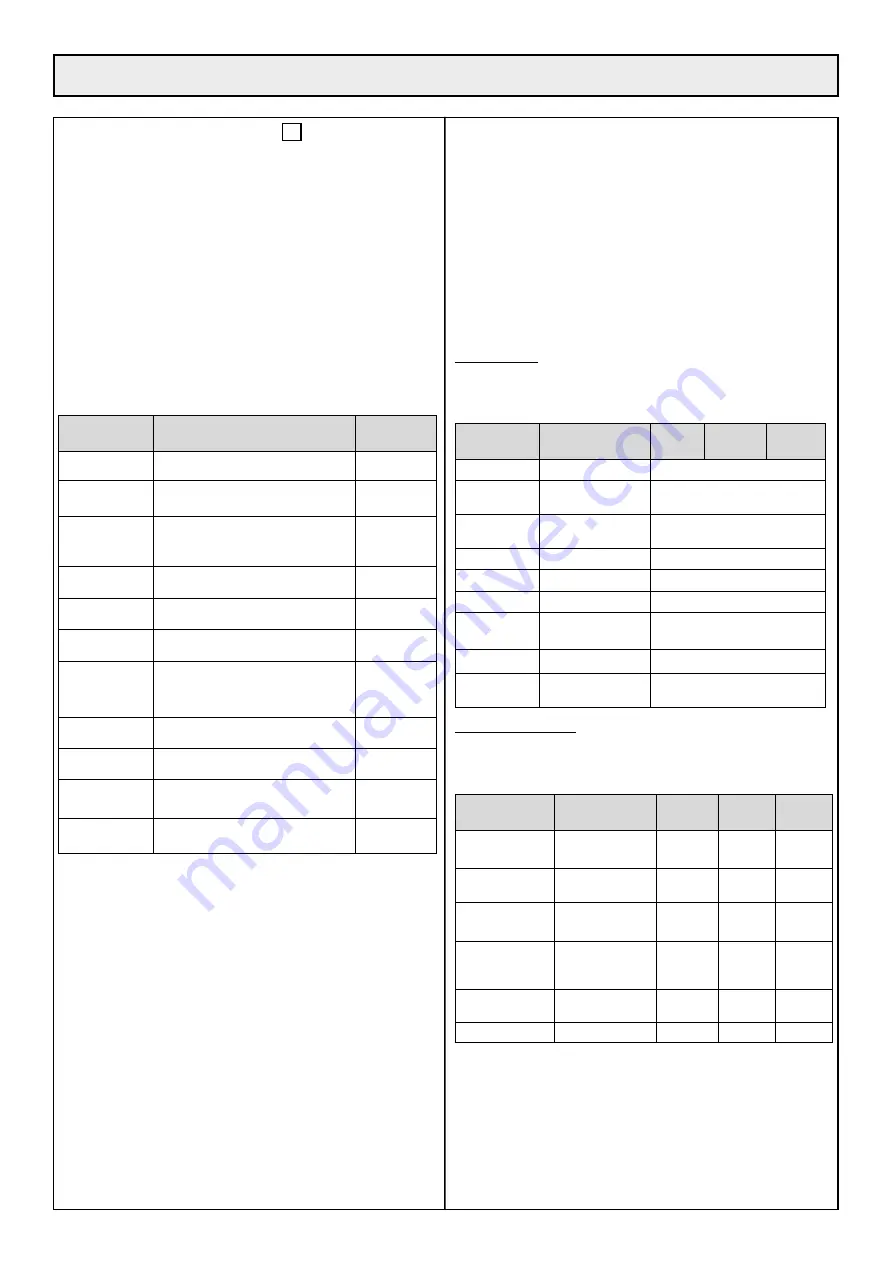
6•4 USER PARAMETERS 

For the multizone option, all the user parameters (table below) are 

defined for each zone. 

Each zone (A, B and C) has its own user 

parameters (except parameter P005 (robot speed) which is a 

global parameter which is identical for all zones).

When the robot chooses a zone to work in, it uses the parameters 

linked to this work zone. This means you can configure the 

installation really flexibly if you consider that 

the multizone robot 

works in each individual zone in exactly the same way as a single 

zone robot using the parameter settings for the zone.

Identification 

(screen)

Significance

Default 

value

P000

Signal sensitivity

30

P001

Length of peripheral wire (x10m) 

ETM105

P002

Maximum distance to follow 

trackborder on leaving the station 

(x10m)

10

P003

Trackborder: minimum segment

0

P004

Trackborder: line

120

P005

Nominal speed

ETM105

P006

Minimum distance to follow 

trackborder on leaving the station 

(x10m)

1

P007

Sensitivity to signal phase

30

P008

Signal frequency channel

0

P009

Distance to follow wire on 

leaving station (x1m)

3

P010

Multizone working time ratio

1

Refer to chapter 4•5 to find out how to change the parameter settings 

using the keyboard.

Only user parameters P008 and P010 have specific details which 

are linked to the multi-zone functionality 

and are described in more 

detail below. The other user parameters are the same as for a single 

zone robot and are not detailed further in this document.

6•4•1 P008 : FREQUENCY CHANNEL

The robot can synchronise itself on the correct peripheral signal 

channel sent via the cable from the station using parameter P008.
For a multizone installation, each zone has its own loop of wire 

connected to a specific board in the station, and for each board, the 

channel is selected using the red channel selector switch (picture 40). 

In order for the multizone installation to work, you need to select 

different values (0, 1, 2, 3, 4, 5) for each zone, A, B and C.
Parameter P008 allows you to synchronise the robot relative to the 

values programmed in the station.

P008 (Zone A) = you have to program the same setting (0, 1, 2, 

3, 4 or 5) as the channel selector in the station board which is 

connected to the loop around Zone A.
P008 (Zone B) as above with the board connected to loop B.
P008 (Zone C) as above with the board connected to loop C.

6•4•2 P010 : WORKING TIME RATIO

See chapter 6•2•6.

6•5 OPTIONS

Using the user parameters (see chapter 6•4), there are options which 

allow the behaviour of the robot to be configured. For a robot with 

multizone software, there are two major categories of options:
Global options: these apply to all the zones (A, B and C) and have 

a unique value which is valid for each zone and each cycle of work. 

They are listed in the table below with their default values: (−) option 

not activated, (√) option activated. 

Identification 

(screen)

Significance

Zone A

Zone B

Zone C

O000

Multi-robots

Global

: (−)

O001

Return to station 

(button F1)

Global

: (−)

O002

Rest at station 

(button F2)

Global

: (−)

O003

Demo mode

Global

: (−)

O004

Silent charge

Global

: (√)

O008

Phase inversion

Global

: (−)

O009

Change of direction 

of cutting heads

Global

: (√)

O016

Multizone

Global

: (−)

O018

Keyboard block 

(SW 2014)

Global

: (−)

Zone-specific options: for each zone (A, B and C), you can configure 

a different setting for a specific option and the robot’s behaviour 

during a work cycle in the given zone depends on the settings for the 

options in this specific zone.

Identification 

(screen)

Significance

Zone A

Zone B Zone C

O010

Anti-clockwise 

return

(−)

(−)

(−)

O011

Return in both 

directions

(√)

(√)

(√)

O013

Return in ‘U’ 

shape

(√)

(√)

(√)

O014

Return following 

the wire 

(SW2014)

(−)

(−)

(−)

O015

Rest time 

disabled

(−)

(−)

(−)

O017

Active zone

(√)

(√)

(√)

Refer to chapter 4•5 to find out how to change the parameter settings 

using the keyboard. 

Only user parameters O8, O15, O16 and O17  have specific 

details which are linked to the multi-zone functionality 

and are 

described in more detail below. The other options are the same as 

for a single zone robot and are not detailed further in this document. 

Options O005, O006, O007 and O012 no longer exist in the latest 

version of the software and are not described.

6• MULTIZONE OPTION 

Summary of Contents for ET MOWER ETM105

Page 1: ...ETM105 ET MOWER GB Original user manual Please read carefully before using your machine...

Page 2: ...AL FOR THE ETM105 ROBOTIC ETESIA 1 Description 15 2 Pictures 16 3 Technical characteristics 20 4 Operating instructions 20 5 Settings 26 6 Multizone Option 28 7 Maintenance 34 8 Troubleshooting 36 INS...

Page 3: ...rations on the recharging station Always turn the main switch to the OFF position before carrying out any operation on the robot Regularly check that the screws which attach the main parts are tightly...

Page 4: ...mower when children animals or people who are unaware are in the mowing area Always leave your robot mower to operate alone Always use suitable protective gloves while working on the robot mower DO NO...

Page 5: ...5 1 KEY TO DIAGRAMS...

Page 6: ...Paths flowerbeds at lawn level between 30 and 50 cm OBSTACLES 2 1 LOCATED MORE THAN 1 M FROM THE EDGE OF THE TERRAIN 2 SOLUTIONS Either the wire passes normally see distances above Or the wire passes...

Page 7: ...ond charger base unit will have to be set up in the second mowing area The robot will be able to travel from one mowing area to the other during its random mowing travel but when the robot looks for t...

Page 8: ...2 3 4 8 If the length of the perimeter wire exceeds the length of a spool of ETESIA ETC or ETC1 wire 500 m a connection will have to be made using an ETK connector according to the procedure described...

Page 9: ...is modified or repaired after the robot is installed due to the wire being cut adding a plot increasing the size of the mowing area and so forth it is imperative to use Etesia ETK connectors to connec...

Page 10: ...turn to the station the machine will go around the island considering the force fields connected to the island as the terrain boundary In case 2 during return to the station the machine will follow it...

Page 11: ...station must be set up on a flat terrain 4 2 CABLING Feed the cables into the rear of the base unit through the cable glands Connect the two ends of the perimeter wire to the JWIRE terminal connector...

Page 12: ...nd or right collision Touch tyre flange Check the red pressure gauge connected in the box Al44 Code expired Follow the code entering procedure Al45 Battery too discharged Put the machine on the statio...

Page 13: ...in a secluded location or in a secondary area Feed the perimeter wires and power cable into the rear of the base unit through the cable glands 14 The station must be positioned on a flat surface of mi...

Page 14: ......

Page 15: ...The robot mower ETM105 is equipped with a display giving a lot of useful information for its use The use of the keypad enables the modification of certain options to optimise the operation e g regula...

Page 16: ...11 17 17 7b 6b 6a 7a 8 9 7c 10 10a 10b 10c 10d 11a 16 2 PICTURES...

Page 17: ...12 13 19 17 15 16 14 18 17 2 PICTURES...

Page 18: ...28 27 26 25 24 23 22 20 21 30 29 31 18 67 cm 67 cm 2 PICTURES ETBA...

Page 19: ...tion wires overlapping one another Zone C Zone C Zone B Zone B Zone B Zone A Zone A Zone A Away from the station minimum 30 cm spacing between wire in ajacent zones Min 3 m Min 3 m Min 3 m Angle dista...

Page 20: ...After a full recharge the robot mower ETM105 automatically begins mowing the lawn again When the lawn does not need mowing the robot mower ETM105 detects it and so it waits at its station indicating...

Page 21: ...of the keypad picture 9 3 Place the robot mower ETM105 on the charging station 4 Type your code _ _ _ _ followed by 5 Let reload manual charge 6 Once charged take the machine out manually 7 Press of t...

Page 22: ...ter 0000 as a new code WARNING when the machine protection is activated you must re enter its code at the end of the validity or the machine stops and requests its code WARNING if you select 0 day you...

Page 23: ...to work ON Switched on Switched off AL Alarm NP New program upgrade The Version menu enables the robot mower ETM105 software version to be obtained The Serial menu enables the serial number of the ma...

Page 24: ...tive zone Option 18 Keyboard lock 4 9 1 OPTION O00 MULTIROBOT The MultiRobot option must be selected if several robots are working in the same area From the OPTIONS screen press F2 and use the again t...

Page 25: ...sses in front of the station before performing a U turn to connect to the station In an S return the robot returns to the station directly without passing in front of it first From the OPTIONS screen...

Page 26: ...mately 15 Beyond this limit the robot mower ETM105 risks slipping in difficult conditions humidity rain uneven density of the terrain etc When the robot mower ETM105 comes to an ascent that is too ste...

Page 27: ...o a suitable differential circuit breaker outside 3 Flat area without obstacles in a 15 m radius 4 5 metres in a straight line on both sides of the station 5 The station must be behind the peripheral...

Page 28: ...e option it is possible to set the system up so that the robot can continue to work on Zones B and C during the competitions at the weekends Or vice versa it can work on Zone A during mid week trainin...

Page 29: ...n a zone and an active period for this zone is about to start the machine returns to the station If the machine is due to leave the station and an active period for the zone is under way or due to sta...

Page 30: ...e to obtain an even cut is proportional to the area of the zone However this rule is only correct if the user does not bias the robot s behaviour by assigning different rest times for the zones Exampl...

Page 31: ...witch picture 40 In order for the multizone installation to work you need to select different values 0 1 2 3 4 5 for each zone A B and C Parameter P008 allows you to synchronise the robot relative to...

Page 32: ...ne mode If it is deactivated default setting the robot can only work in a single zone It reverts to being a single zone robot Even if the ins tallation contains multiple wire loops the robot will alwa...

Page 33: ...10 If option 0016 Multizone is not activated only Global Menu and Menu Zone A are visible Option O016 can be activated from the Global Menu 6 7 2 GLOBAL SUB MENU When the Global menu is displayed you...

Page 34: ...m to minimise the recovery area see chapter 6 1 This zone is where there is significant overlap between the different signals and minimising the area is recommended in order to reduce magnetic interfe...

Page 35: ...tate to contact your dealer 7 5 1 CHANGING THE CUTTING BLADES PROGRESS MEANINGS 1 Machine OFF protective gloves 2 Straighten the machine 3 Put the hole of the disc opposite the screw head of the blade...

Page 36: ...nsult your dealer The machine carries out squares systematically The grass is too high in one area of the lawn and the machine deals with this area systematically You simply need to check that grass o...

Page 37: ...to its station and has been disconnected from it Check that the charging contacts of the station and the machine have not been oxidized Check that the station has not been set up on a slope Warning if...

Page 38: ...t its station for a long time and does not leave it again The machine has nothing left to mow and stays at the station Check whether the machine display mentions SC Slow Charge the machine starts its...

Page 39: ......

Page 40: ...nt through SMS to the robot This manual applies to the robots and modules programmed with the firmware version of Release 2013 or later 3 1 OVERVIEW SMS COMMANDS AND ALARMS LIST OF SMS COMMANDS Functi...

Page 41: ...OL_PHONE numbers are defined they are both set with the number of the phone which sent this command ClearCtrlPhone will clear the CONTROL_PHONE number so it can be assigned to a new number The command...

Page 42: ...nswering confirmation that ALARM_PHONE has been cleared 3 3 GETTING INFORMATION FROM THE ROBOT THROUGH SMS The 3 commands Status Position and MowerData can be sent from any phone number The sender is...

Page 43: ..._PHONE or from the CONTROL_PHONE or from another phone if ALARM_PHONE or CONTROL_PHONE are not defined and the sender is receiving a confirmation SMS with some informations The Mowerdata command is ca...

Page 44: ...be effective Those commands can only be sent from the ALARM_PHONE or from the CONTROL_PHONE or from any phone if CONTROL_ PHONE is not defined A confirmation SMS is sent to the calling phone and the...

Page 45: ...to the parameter passed in the command The virtual fence commands can only be sent by the ALARM_ PHONE If the ALARM_PHONE is not yet defined it is set to the number that issued the Setfence command A...

Page 46: ...al operation or after a 15 period of keyboard inactivity Security threat detection robot leaving the zone defined by the virtual fence see section 3 6 or GPS GPRS module detecting abnormal move speed...

Page 47: ...t DATA history of the robot To download the data to be inserted in the Dealer Tool Suite software DTS Select the file and download it Save it and unzip it before introducing in DTS E mail Download Gro...

Page 48: ...l Input Output Motion Miscellaneous Timer 1 Filter Selection Events Geozone 4 3 PAGE MAP 4 3 1 FILTER ICON To choose a position several positions a date or a range of specific dates to determine what...

Page 49: ...ng the search tool Check the box Click on the Update icon 4 3 3 HISTORY ICON To display the last events of the selected robot see picture below 4 3 4 UPDATE ICON To update the data 4 3 5 HOME ICON To...

Page 50: ...in the Map description Select the range of date for which you want to see the information Click on Show Map Type Week Map description Employee Trip type Event User Filter Full Data Full Data 35 Search...

Page 51: ...s occurring continuously Only one Alarm_SMS is sent in those conditions see section 3 7 The robot is switched off I can see it through Status command but I did not receive the corresponding SMS messag...

Page 52: ...r to ETESIA robot user manual The clock that the Track Trace module is capturing directly from the GPS satellites The clock that the Track Trace module keeps updated without the GPS reference The cloc...

Page 53: ...fault recognized by ETESIA as such will be eligible to warranty parts and labour It will therefore be paid back to the dealer according to charge scale mentioned in the agreement It is dealer responsi...

Page 54: ...2014 35 UE from 26 02 14 Electrical material intended to be employed in certain limits of tension M TREGER Claude 13 rue de l industrie 67165 Wissembourg CEDEX is the person authorized to constitute...

Page 55: ...ETESIA SERVICE GARANTIE 13 rue de l Industrie 67165 WISSEMBOURG CEDEX France Stamp here please...

Page 56: ...m2 Date_________________________ Signature____________________ Signature and confirmation of the user that he has taken possession of a machine in perfect working order that the user has been handed...

Reviews: