background image

29

6•2•2 DESCRIPTION OF THE PARAMETERS / 

OPTIONS  

They allow the user to control the algorithm used by the robot to 

define its work zone. The other parameters / options and the menu 

navigation method are described in chapters 4•5, 6•4 and 6•5. 

6•2•3 REST AT STATION FOR SEVERAL CYCLES 

(BACKHOME OPTION 2, F2 BUTTON)

Station rest (backhome = on charge) has priority over all other 

options and a robot for which option O2 has been enabled will rest at 

the station permanently until a new order is received from the user. 

So this option applies globally across all zones (A, B and C).
Sending a ‘Backhome’ SMS (Track&Trace manual) enables the O2 

option and forces the robot to stay at the station. Sending a ‘Restart’ 

SMS disables the O2 option and allows the robot to work. It is the 

other parameters / options described below which affect how the 

multizone robot behaves.

6•2•4 “ACTIVE ZONE” OPTION (OPTION 17)

A machine never works in a zone if the zone has been disabled. 

This option O17 is considered as a 2nd priority (after option O2 

backhome) in the algorithm which decides which zones the robot will 

work on.
If the machine is working in a zone and a user disables it, the 

machine returns directly to the station. This amounts to a return to 

station (step 1 of the figure 1). 
If the machine is in the station and decides to leave, it will never select 

a zone which has been disabled by the user (step 5 of the figure 1).
The possible values for option 17 are: 

Option 17 (Zone X) = 0: Zone X (X=A, B or C) is disabled.


The machine does not work in zone X. Even if a zone is disabled, 

all the parameters, options and resting times relative to this zone 

are stored in the robot’s memory. So when the zone is re-enabled 

(Option 17 =1), there is no reprogramming to do.

Sending a ‘Disablezone X’ SMS (X = A, B or C) is equivalent to set-

ting option 17 to a value of 0.

Option 17 (Zone X) = 1: Zone X (X=A, B or C) is enabled. 

Sending an ‘Enablezone X’ SMS (X = A, B or C) is equivalent to 

setting option 17 to a value of 1.

6•2•5 REST TIME AND “NO RESTS” OPTION  

(OPTION 15)

A machine never works in zone X (X= A, B or C) if:

The current time is part of a rest time programmed for zone X. It 

should be noted that the rest times can be programmed for each 

zone and verified via DTS (DTS5.x or DTS6.X) that the rest times 

are those required for each of the zones.


AND

 the rest times for zone X are enabled (Option 15 (ZoneX)=0).

The active periods of time are considered as a 3rd priority (after 

option O2 backhome and option O17 zone active) in the algorithm 

which decides which zones the robot will work on.
If the machine is working in a zone and an active period for this zone 

is about to start, the machine returns to the station.
If the machine is due to leave the station and an active period for the 

zone is under way (or due to start within 10 minutes), the machine 

will not select this zone for the next mowing cycle.

The possible values for option 15 are:

Option 15 (Zone X) = 0: The rest times programmed for 

zone Z are active, i.e. the robot takes them into consideration 

and cannot work in zone X during these periods. 

Sending a 

‘TimerOn’ text is equivalent to setting option 15 to 0 for all the 

zones (A, B and C). Sending a ‘TimerOn X’ SMS (X = A, B or C) 

is equivalent to setting option 15 to 0 for Zone X alone.

Option 15 (Zone X) = 1: The rest times programmed for zone 

X are disabled, i.e. the robot does not take into consideration 

the rest times for zone X and can work in this area at any time.


Even if the periods are disabled, the programming is stored in the 

robot’s memory and all that is required to reactivate them is to set 

option 15 to 0. The periods do not need to be programmed again. 

Sending a ‘TimerOff’ text is equivalent to setting option 15 to 1 

for all the zones (A, B and C). Sending a ‘TimerOff X’ SMS (X = 

A, B or C) is equivalent to setting option 15 to 1 for Zone X alone.

Example use of rest time in multizone mode:
Let’s consider a multizone installation with 2 zones: zone A and zone B.
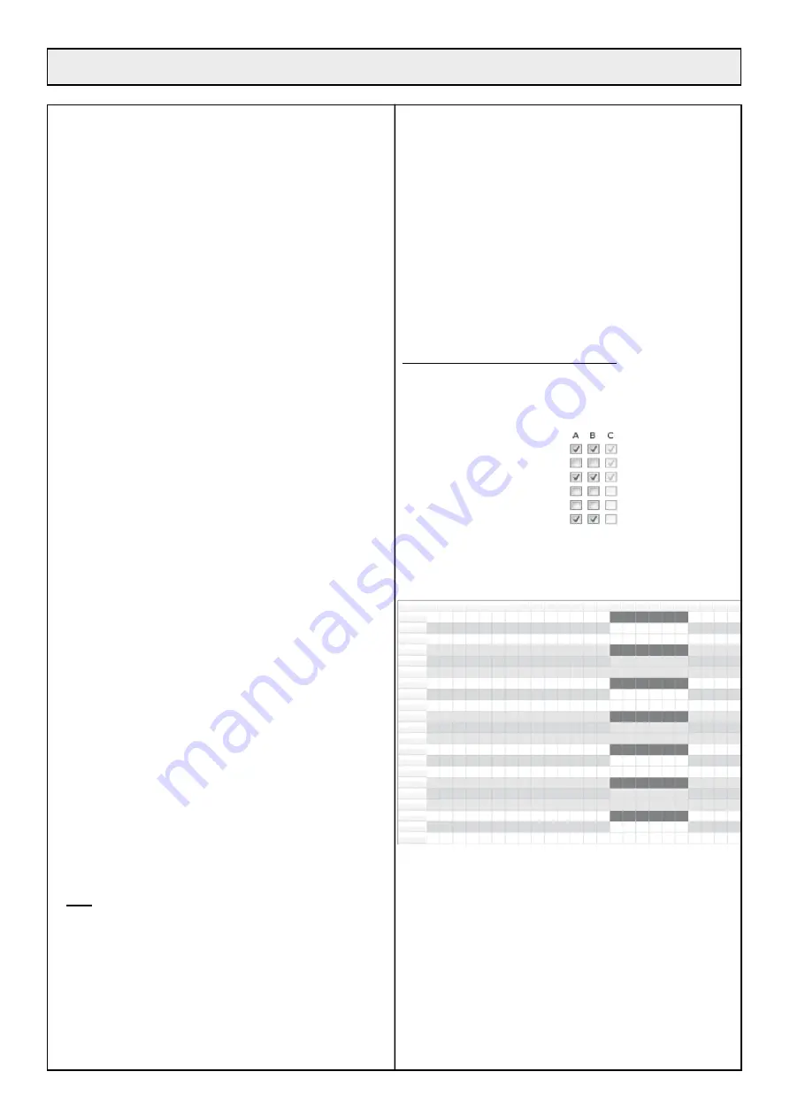
Using the keyboard, the user has programmed options 15 and 17 as 

follows (DTS6.X screen capture):

O10 - CCWSeek

O11 - Chge2Sides

O13 - Udocking 

O14 - Back Along Wire

O15 - No Rests

O17 - Enable Zone

The two zones A and B are active (Option 17 = 1) and the rest times 

for the two zones A and B are active (Option 15 = 0). The time 

periods for the two zones in question have been programmed using 

the keyboard based on the system below (DTS6.x screen capture):

Rest time 

Rest time 

Rest time 

Rest time 

Rest time 

Rest time 

Rest time 

00h

Monday

Tuesday

Wednesday

Thursday 

Friday 

Saturday 

Sunday 

01h 02h 03h 04h 05h 06h 07h 08h 09h 10h 11h 12h 13h 14h 15h 16h 17h 18h 19h 20h 21h 22h 23h

Every day, between 14:00 and 20:00, a rest period has been defined 

for zone A (black bars above). Given that the periods are activated 

for this zone (Option 15 (zoneA)=0), the robot will not go into zone 

A between 14:00 and 20:00. During this period, it will work conti-

nuously in zone B which does not have an active period between 

14:00 and 20:00.

In the same way, between 20:00 and 14:00, the robot will only work 

in zone A because it cannot work in zone B (rest time and option 15 

(ZoneB) = 0).

In the example above, the time periods are mutually exclusive. So at 

any time, the robot can only choose one of the two zones to work in 

and applying P10 parameters (the value of P10 parameters) has no 

influence on where the robot works. 

6• MULTIZONE OPTION 

Summary of Contents for ET MOWER ETM105

Page 1: ...ETM105 ET MOWER GB Original user manual Please read carefully before using your machine...

Page 2: ...AL FOR THE ETM105 ROBOTIC ETESIA 1 Description 15 2 Pictures 16 3 Technical characteristics 20 4 Operating instructions 20 5 Settings 26 6 Multizone Option 28 7 Maintenance 34 8 Troubleshooting 36 INS...

Page 3: ...rations on the recharging station Always turn the main switch to the OFF position before carrying out any operation on the robot Regularly check that the screws which attach the main parts are tightly...

Page 4: ...mower when children animals or people who are unaware are in the mowing area Always leave your robot mower to operate alone Always use suitable protective gloves while working on the robot mower DO NO...

Page 5: ...5 1 KEY TO DIAGRAMS...

Page 6: ...Paths flowerbeds at lawn level between 30 and 50 cm OBSTACLES 2 1 LOCATED MORE THAN 1 M FROM THE EDGE OF THE TERRAIN 2 SOLUTIONS Either the wire passes normally see distances above Or the wire passes...

Page 7: ...ond charger base unit will have to be set up in the second mowing area The robot will be able to travel from one mowing area to the other during its random mowing travel but when the robot looks for t...

Page 8: ...2 3 4 8 If the length of the perimeter wire exceeds the length of a spool of ETESIA ETC or ETC1 wire 500 m a connection will have to be made using an ETK connector according to the procedure described...

Page 9: ...is modified or repaired after the robot is installed due to the wire being cut adding a plot increasing the size of the mowing area and so forth it is imperative to use Etesia ETK connectors to connec...

Page 10: ...turn to the station the machine will go around the island considering the force fields connected to the island as the terrain boundary In case 2 during return to the station the machine will follow it...

Page 11: ...station must be set up on a flat terrain 4 2 CABLING Feed the cables into the rear of the base unit through the cable glands Connect the two ends of the perimeter wire to the JWIRE terminal connector...

Page 12: ...nd or right collision Touch tyre flange Check the red pressure gauge connected in the box Al44 Code expired Follow the code entering procedure Al45 Battery too discharged Put the machine on the statio...

Page 13: ...in a secluded location or in a secondary area Feed the perimeter wires and power cable into the rear of the base unit through the cable glands 14 The station must be positioned on a flat surface of mi...

Page 14: ......

Page 15: ...The robot mower ETM105 is equipped with a display giving a lot of useful information for its use The use of the keypad enables the modification of certain options to optimise the operation e g regula...

Page 16: ...11 17 17 7b 6b 6a 7a 8 9 7c 10 10a 10b 10c 10d 11a 16 2 PICTURES...

Page 17: ...12 13 19 17 15 16 14 18 17 2 PICTURES...

Page 18: ...28 27 26 25 24 23 22 20 21 30 29 31 18 67 cm 67 cm 2 PICTURES ETBA...

Page 19: ...tion wires overlapping one another Zone C Zone C Zone B Zone B Zone B Zone A Zone A Zone A Away from the station minimum 30 cm spacing between wire in ajacent zones Min 3 m Min 3 m Min 3 m Angle dista...

Page 20: ...After a full recharge the robot mower ETM105 automatically begins mowing the lawn again When the lawn does not need mowing the robot mower ETM105 detects it and so it waits at its station indicating...

Page 21: ...of the keypad picture 9 3 Place the robot mower ETM105 on the charging station 4 Type your code _ _ _ _ followed by 5 Let reload manual charge 6 Once charged take the machine out manually 7 Press of t...

Page 22: ...ter 0000 as a new code WARNING when the machine protection is activated you must re enter its code at the end of the validity or the machine stops and requests its code WARNING if you select 0 day you...

Page 23: ...to work ON Switched on Switched off AL Alarm NP New program upgrade The Version menu enables the robot mower ETM105 software version to be obtained The Serial menu enables the serial number of the ma...

Page 24: ...tive zone Option 18 Keyboard lock 4 9 1 OPTION O00 MULTIROBOT The MultiRobot option must be selected if several robots are working in the same area From the OPTIONS screen press F2 and use the again t...

Page 25: ...sses in front of the station before performing a U turn to connect to the station In an S return the robot returns to the station directly without passing in front of it first From the OPTIONS screen...

Page 26: ...mately 15 Beyond this limit the robot mower ETM105 risks slipping in difficult conditions humidity rain uneven density of the terrain etc When the robot mower ETM105 comes to an ascent that is too ste...

Page 27: ...o a suitable differential circuit breaker outside 3 Flat area without obstacles in a 15 m radius 4 5 metres in a straight line on both sides of the station 5 The station must be behind the peripheral...

Page 28: ...e option it is possible to set the system up so that the robot can continue to work on Zones B and C during the competitions at the weekends Or vice versa it can work on Zone A during mid week trainin...

Page 29: ...n a zone and an active period for this zone is about to start the machine returns to the station If the machine is due to leave the station and an active period for the zone is under way or due to sta...

Page 30: ...e to obtain an even cut is proportional to the area of the zone However this rule is only correct if the user does not bias the robot s behaviour by assigning different rest times for the zones Exampl...

Page 31: ...witch picture 40 In order for the multizone installation to work you need to select different values 0 1 2 3 4 5 for each zone A B and C Parameter P008 allows you to synchronise the robot relative to...

Page 32: ...ne mode If it is deactivated default setting the robot can only work in a single zone It reverts to being a single zone robot Even if the ins tallation contains multiple wire loops the robot will alwa...

Page 33: ...10 If option 0016 Multizone is not activated only Global Menu and Menu Zone A are visible Option O016 can be activated from the Global Menu 6 7 2 GLOBAL SUB MENU When the Global menu is displayed you...

Page 34: ...m to minimise the recovery area see chapter 6 1 This zone is where there is significant overlap between the different signals and minimising the area is recommended in order to reduce magnetic interfe...

Page 35: ...tate to contact your dealer 7 5 1 CHANGING THE CUTTING BLADES PROGRESS MEANINGS 1 Machine OFF protective gloves 2 Straighten the machine 3 Put the hole of the disc opposite the screw head of the blade...

Page 36: ...nsult your dealer The machine carries out squares systematically The grass is too high in one area of the lawn and the machine deals with this area systematically You simply need to check that grass o...

Page 37: ...to its station and has been disconnected from it Check that the charging contacts of the station and the machine have not been oxidized Check that the station has not been set up on a slope Warning if...

Page 38: ...t its station for a long time and does not leave it again The machine has nothing left to mow and stays at the station Check whether the machine display mentions SC Slow Charge the machine starts its...

Page 39: ......

Page 40: ...nt through SMS to the robot This manual applies to the robots and modules programmed with the firmware version of Release 2013 or later 3 1 OVERVIEW SMS COMMANDS AND ALARMS LIST OF SMS COMMANDS Functi...

Page 41: ...OL_PHONE numbers are defined they are both set with the number of the phone which sent this command ClearCtrlPhone will clear the CONTROL_PHONE number so it can be assigned to a new number The command...

Page 42: ...nswering confirmation that ALARM_PHONE has been cleared 3 3 GETTING INFORMATION FROM THE ROBOT THROUGH SMS The 3 commands Status Position and MowerData can be sent from any phone number The sender is...

Page 43: ..._PHONE or from the CONTROL_PHONE or from another phone if ALARM_PHONE or CONTROL_PHONE are not defined and the sender is receiving a confirmation SMS with some informations The Mowerdata command is ca...

Page 44: ...be effective Those commands can only be sent from the ALARM_PHONE or from the CONTROL_PHONE or from any phone if CONTROL_ PHONE is not defined A confirmation SMS is sent to the calling phone and the...

Page 45: ...to the parameter passed in the command The virtual fence commands can only be sent by the ALARM_ PHONE If the ALARM_PHONE is not yet defined it is set to the number that issued the Setfence command A...

Page 46: ...al operation or after a 15 period of keyboard inactivity Security threat detection robot leaving the zone defined by the virtual fence see section 3 6 or GPS GPRS module detecting abnormal move speed...

Page 47: ...t DATA history of the robot To download the data to be inserted in the Dealer Tool Suite software DTS Select the file and download it Save it and unzip it before introducing in DTS E mail Download Gro...

Page 48: ...l Input Output Motion Miscellaneous Timer 1 Filter Selection Events Geozone 4 3 PAGE MAP 4 3 1 FILTER ICON To choose a position several positions a date or a range of specific dates to determine what...

Page 49: ...ng the search tool Check the box Click on the Update icon 4 3 3 HISTORY ICON To display the last events of the selected robot see picture below 4 3 4 UPDATE ICON To update the data 4 3 5 HOME ICON To...

Page 50: ...in the Map description Select the range of date for which you want to see the information Click on Show Map Type Week Map description Employee Trip type Event User Filter Full Data Full Data 35 Search...

Page 51: ...s occurring continuously Only one Alarm_SMS is sent in those conditions see section 3 7 The robot is switched off I can see it through Status command but I did not receive the corresponding SMS messag...

Page 52: ...r to ETESIA robot user manual The clock that the Track Trace module is capturing directly from the GPS satellites The clock that the Track Trace module keeps updated without the GPS reference The cloc...

Page 53: ...fault recognized by ETESIA as such will be eligible to warranty parts and labour It will therefore be paid back to the dealer according to charge scale mentioned in the agreement It is dealer responsi...

Page 54: ...2014 35 UE from 26 02 14 Electrical material intended to be employed in certain limits of tension M TREGER Claude 13 rue de l industrie 67165 Wissembourg CEDEX is the person authorized to constitute...

Page 55: ...ETESIA SERVICE GARANTIE 13 rue de l Industrie 67165 WISSEMBOURG CEDEX France Stamp here please...

Page 56: ...m2 Date_________________________ Signature____________________ Signature and confirmation of the user that he has taken possession of a machine in perfect working order that the user has been handed...

Reviews: