background image

ETAS

Basic Safety Notices

FETK-S2.1 - User’s Guide

9

2

Basic Safety Notices

This chapter contains information about the following topics:

• “General Safety Information” on page 9
• “Requirements for Users and Duties for Operators” on page 9
• “Intended Use” on page 9
• “Identifications on the Product” on page 13
• “Taking the Product Back and Recycling” on page 14
• “CE  marking”  on  page 14
• “RoHS Conformity” on page 14
• “Declarable Substances” on page 15
• “Use of Open Source Software” on page 15

2.1

General Safety Information

Please observe the Product Safety Notices ("ETAS Safety Notice") and the fol-
lowing safety notices to avoid health issues or damage to the device. 

ETAS GmbH does not assume any liability for damages resulting from 
improper handling, unintended use or non-observance of the safety precau-
tions.

2.2

Requirements for Users and Duties for Operators

The product may be assembled, operated and maintained only if you have the 
necessary qualification and experience for this product. Improper use or use by 
a user without sufficient qualification can lead to damages or injuries to one's 
health or damages to property.
The safety of systems using the product is the responsibility of the system inte-
grator.

General Safety at Work

The existing regulations for safety at work and accident prevention must be 
followed. All applicable regulations and statutes regarding operation must be 
strictly followed when using this product.

2.3

Intended Use

An ETK is an electronic component that is installed in a vehicle control unit 
(ECU) to read data from the ECU or write data to the ECU.

NOTE

Carefully read the documentation (Product Safety Advice and this User's 
Guide) that belongs to the product prior to the startup.

Summary of Contents for FETK-S2.1

Page 1: ...www etas com FETK S2 1 Emulator Probe for MPC57xx and EMU57xx MCU Family User s Guide...

Page 2: ...or single license Using and copying is only allowed in concurrence with the specifications stipulated in the contract Under no circumstances may any part of this document be copied reproduced transmit...

Page 3: ...y 14 2 7 1 European Union 14 2 7 2 China 14 2 8 Declarable Substances 15 2 9 Use of Open Source Software 15 3 Introduction 16 3 1 Applications 16 3 2 Features 17 4 Hardware Description 19 4 1 Architec...

Page 4: ...al Conditions 35 7 5 Power Supply 36 7 6 Test Characteristics 36 7 7 JTAG Timing Characteristics 37 7 7 1 JTAG Timing Diagram 37 7 7 2 JTAG Timing Parameters 37 7 8 Electrical Characteristics 38 7 8 1...

Page 5: ...ons 54 8 8 3 Connectors 54 8 8 4 Temperature Range 54 8 8 5 Ordering 54 8 9 ETAM8 Adapter 55 8 9 1 Usage 55 8 9 2 Pin Numbering 55 8 9 3 ECU Connector Signal Modes 56 8 9 4 Temperature Range 56 8 9 5...

Page 6: ...2 9 Ordering Information 63 9 1 FETK S2 1 63 9 2 Cable 63 9 2 1 ECU Adapter Cable 63 9 2 2 ECU Adapter and Power Supply Cable 64 9 2 3 GBit Ethernet and Power Supply Cable 65 9 2 4 ECU Adapter 65 9 2...

Page 7: ...ry steps for this are in a step by step guide Target definition 1 Step 1 2 Step 2 3 Step 3 Result DANGER indicates a hazardous situation with a high risk of death or serious injury if not avoided WARN...

Page 8: ...Click OK Buttons are shown in boldface Press ENTER Keyboard commands are shown in angled brackets The Open File dialog box is displayed Names of program windows dialog boxes fields etc are shown in qu...

Page 9: ...n observance of the safety precau tions 2 2 Requirements for Users and Duties for Operators The product may be assembled operated and maintained only if you have the necessary qualification and experi...

Page 10: ...safely disconnected from the supply voltage For example use a car battery or a suitable lab power supply Use only lab power supplies with double protection to the supply system Ensure that the connect...

Page 11: ...lvents or abra sive cleaners which could damage the product Transport and Installation CAUTION Danger from inadvertent current flow Depending on the design the shield of the Ethernet cables can be con...

Page 12: ...ment of the cables to the connectors Detailed information about cabling is located in the ETK User s Guides CAUTION Differences in case ground potentials can cause high currents to flow through the sh...

Page 13: ...14 Symbol for CE conformity see chapter 2 6 on page 14 Symbol for China RoHS see chapter 2 7 2 on page 14 Symbol for China RoHS see chapter 2 7 2 on page 14 Symbol for electrostatic sensitive componen...

Page 14: ...ched to the product or its packaging ETAS confirms that the product corresponds to the applicable product specific European Direc tives The CE Declaration of Conformity for the product is available up...

Page 15: ...oad center in the customer information REACH Declaration www etas com Reach This information is continuously being updated 2 9 Use of Open Source Software The product uses Open Source Software OSS Thi...

Page 16: ...U the FETK S2 1 has to be connected via ES89x modules The system can be used for high speed Measurement Calibration and ECU flash programming Support of Rapid Prototyping applications e g functional p...

Page 17: ...reset Pin less ECU handshake and trigger mechanism Hook based DISTAB and hook less measurement approaches Calibration Concurrent use of calibration and measurement performed via micro controller debug...

Page 18: ...haracteristics ETK Drivers and Tools update to support ETAS software tools INCA XCT Firmware update programming of the logic device through HSP soft ware service packs removal of FETK or ECU is not ne...

Page 19: ...the cali bration and development system by buffering the data DISTAB17 and triggering the FETK to read the data via JTAG or LFAST The FETK then reads buffers processes and sends this measured data to...

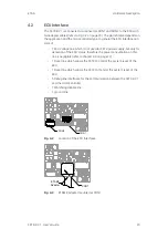
Page 20: ...d for FETK power supply but only for detection of the ECU status therefore the power consumption on this line is negligible refer to chapter 4 4 on page 22 1 Reset line which allows the FETK to contro...

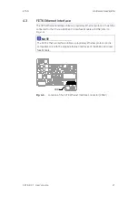
Page 21: ...t protocol It has to be connected to the PC via a ES89x ECU Interface Module at CON3 refer to Fig 4 4 Fig 4 4 Location of the FETK Ethernet Interface connector CON3 NOTE The FETK Ethernet interface ut...

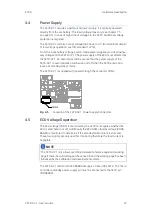
Page 22: ...itched on and off when the FETK enters and leaves its standby sleep mode The FETK S2 1 is supplied with power through the connector CON2 Fig 4 5 Location of the FETK S2 1 Power Supply Connectors 4 5 E...

Page 23: ...ng the corresponding data in the Flash to the emula tion space To enable calibration the Working Page must be activated The process of switching from the Reference Page to the Working Page and vice ve...

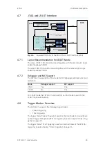
Page 24: ...e Pinless Triggering uses the microcontroller s internal Devel opment Trigger Semaphore DTS for triggering See also chapter Pinless Trig gering on page 25 The trigger mode Timer Triggering uses four i...

Page 25: ...APHORE corresponds to an FETK hardware trigger Within the FETK s configuration and or A2L file bit 0 corresponds to hardware trigger 1 and bit 63 corresponds to hardware trigger 64 The FETK periodical...

Page 26: ...ORST and RESETOUT of the microcontroller are used by the FETK S2 1 to detect when the ECU is in reset The FETK S2 1 senses the switched ECU power supply This allows it to detect when the ECU is off an...

Page 27: ...separately refer chapter Ordering Infor mation on page 63 Fig 5 1 FETK S2 1 Connection to the ECU CAUTION Some components of the interface board may be damaged or destroyed by electrostatic discharges...

Page 28: ...ace The FETK Ethernet interface can be connected to the ES89x ECU and Interface Module NOTE The FETK Ethernet interface utilizes a proprietary Ethernet protocol and is compatible only with the Gigabit...

Page 29: ...er Supply wiring with CBAM320 1 Cable EC U ECUG N D EC U C o n n e cto r FETK P ow erSu p p lyCon n ector V eh icle Battery Veh icle W irin g Se rialETKInte rface C onne ctor C ableC B A M 300 3 E g C...

Page 30: ...ed Power Supply inside ECU ECU ECU GND ECU Connector FETK Power Supply Connector Vehicle Battery Vehicle Wiring Serial ETK Interface Connector Cable CBAM350 1 E g Cable CBE260 Lemo Socket DC DC ECU Ig...

Page 31: ...ts these inputs can be downloaded from this database If necessary a plausibility check is performed 2 Connection of the ETK XETK FETK to the ECU The ECU hardware developer defines the connection of th...

Page 32: ...ifferent ETK XETK FETK types in the help docu ment of the XCT Starting the XCT help 1 Start XCT The main window of XCT opens 2 Select in the menu bar Contents The XCT help window opens 3 Choose Refere...

Page 33: ...the Power Manage ment register Confirm your configuration The manufacturers of network adapter have different names for this function Example Link down Power saving Allow the computer to turn off thi...

Page 34: ...ED RAM is capable of being powered using a standby supply MPC5746R ED 1 V11 8 0 V7 2 8 V4 1 9 V6 4 3 V4 6 2 MPC5746R V11 8 0 V7 2 8 V4 1 9 V6 4 3 V4 6 2 SPC58NN84 V11 8 0 V7 2 8 V4 1 9 V6 4 3 V4 6 2 E...

Page 35: ...software Item Characteristics Connection 1 Gbit s Ethernet Cable length max 30 m 100 ft Ethernet Interface DC decoupling NOTE The FETK Ethernet interface utilizes a proprietary Ethernet protocol and...

Page 36: ...t 12 V I 500 mA at pin VDDSTBY 1 25 V I 80 mA at Pin VDDPSTBY T 20 C 2 4 W 1 The FETK S2 1 implements reverse voltage protection in the same range and may be used only with central load dump protectio...

Page 37: ...ce level of 1 5 V Output signals are mea sured with 20 pF to ground and 50 to 1 5 V Parameter Symbol Value ns Comment JTAG Clock Period ETK Target ttck 50 20 MHz Nexus JTAG Clock Frequency 25 40 MHz N...

Page 38: ...6 V to 36 V load 0 to 50 mA Ubatt 1 V Ubatt V ECU Power Supply Supervision Voltage 3 3 V selected VDDP ECU on 2 67 2 77 2 89 V ECU off 2 44 2 56 2 68 V IDDP VDDP 3 3 V 800 A ECU Standby RAM Supervisio...

Page 39: ...by ETK typ pF 1 TCK XO 2 0 7 3 8 5 2 6 5 1135 810 15 TMS XO 2 0 7 3 8 5 2 6 5 60 60 25 TDO I 0 8 2 6 5 50 50 27 TDI XO 2 0 7 3 8 5 2 6 5 40 40 21 TRST XO 2 0 7 3 8 5 2 6 5 40 40 23 ESR0 IXOD 3 0 7 0 8...

Page 40: ...1 TRST XO 2 0 7 2 4 3 45 6 5 40 40 23 ESR0 IXOD 3 0 7 0 8 2 6 5 25 20 15 PORST IXOD 3 0 7 0 8 2 6 5 25 20 15 WDGDIS XO 2 0 7 2 4 3 45 6 5 10 10 10 1 Adapter cable and Samtec connector not considered P...

Page 41: ...nput JTAG Signal 2 TRST Output JTAG Signal 11 ESR0 Bidir ECU Reset signal open drain for Reset assertion and supervision 13 PORST Bidir ECU Power On Reset signal open drain for Reset assertion and sup...

Page 42: ...ignal open drain for Reset assertion and supervision 5 WDGDIS Output Watchdog disable Signal 18 GATE_PORST Input Input Overwrite PORST status at Power On 7 VDDP Sense Input Sense for Switched power su...

Page 43: ...ht 1 13 1 0 5157 1 CBAM300 CBAM305 CBAM340 mounted at CON3 Item Dimension Millimeters Tolerance Millimeters Dimension Inches Tolerance Inches A 41 50 0 20 1 634 0 008 B 35 90 0 30 1 413 0 012 C 31 50...

Page 44: ...r s Guide 44 7 10 2 Side View Fig 7 4 FETK S2 1 Dimensions Side View Item Dimension Millimeters Tolerance Millimeters Dimension Inches Tolerance Inches A 4 20 0 10 0 165 0 004 B 1 60 0 16 0 063 0 006...

Page 45: ...age 54 ECU Adapter ETAM8 Adapter on page 55 Power Supply Cable ETV5 Cable on page 57 ETAM2 Adapter on page 58 ETAM5 Adapter on page 59 ETAM9 Adapter on page 60 ETAM10 Adapter on page 61 8 2 Requiremen...

Page 46: ...nt the cable with a nut not included SM PE 9 order number 52103210 from Lapp For wall thickness more than 4 mm cut a thread into the housing 8 3 2 Connectors Fig 8 2 CBAM300 3 Cable Connectors 8 3 3 T...

Page 47: ...h boring with 9 2 mm in the housing and mount the cable with a nut included For wall thickness more than 4 mm cut a thread into the housing A spe cial Lemo thread cutter is necessary 8 4 2 Connectors...

Page 48: ...ig 8 6 CBAM340 Cable Connectors 8 5 3 Temperature Range 8 5 4 Ordering NOTE The hardware for mounting ECU adapter cables is not included in the cable delivery they need to be ordered separately For de...

Page 49: ...nnected to socket It is usable for ECUs with shielded housing 8 6 2 Panel Cut Out Fig 8 8 Dimension Panel Cut Out 8 6 3 Assembling A Lemo tool type Lemo Spanner DCH 91 161 PA is needed for assembling...

Page 50: ...bles and Accessories FETK S2 1 User s Guide 50 8 6 4 Temperature Range 8 6 5 Ordering Condition Temperature Operating temperature 40 C to 125 C Product Length Order Number CBAM350 1 0m17 0 17 m F 00K...

Page 51: ...with 15 2 mm in the hous ing and mount the cable with a nut not included SM PE 9 Order num ber 52103210 from Lapp For wall thickness more than 4mm cut a thread into the housing If the CBAM305 1 2m2 i...

Page 52: ...12 CBAM305 1 2m2 Connectors Connector Color Target CON1 Blue lila Gbit Ethernet cable e g CBE260 CON2 White FETK CON3 Black Permanent power supply K70 1 cable CON4 Red FETK UBATT Connector Color Targ...

Page 53: ...e 53 8 7 4 Temperature Range 8 7 5 Tightness 8 7 6 Ordering Condition Temperature Operating temperature 40 C to 125 C Condition IP Code PG9 screwing IP67 Product Length Order Number CBAM305 1 0m6 0 6...

Page 54: ...FETK or another ES device The cable supports power propagation 8 8 2 Dimensions 8 8 3 Connectors Fig 8 14 CBE260 Connectors 8 8 4 Temperature Range 8 8 5 Ordering Short Name Length A CBE260 1 3 300 c...

Page 55: ...FM 105 con nector to a BR_XETK S FETK S or FETK T There are two variants for the ETAM8 adapter available ETAM8A hold the ECU in Reset while the ETK is booting ETAM8B do not pull the Reset low while bo...

Page 56: ...Mode DAP Mode 1 GND GND GND 2 TCK DRCLK DAP0 3 TRST RXD TRST 4 TDO RXD DAP2 5 TMS TXD DAP1 6 TDI TXD 7 WDGDIS WDGDIS WDGDIS 8 VDD Sense VDD Sense VDD Sense 9 RESETOUT RESETOUT RESETOUT 10 PORESET PORE...

Page 57: ...8 10 2 Pin Assignment 8 10 3 Temperature Range 8 10 4 Ordering NOTE For better power integrity cut the cable to the shortest possible length Pin Number Color Signal Description 1 Not connected 2 Not c...

Page 58: ...details on mating connector to the ETAM2 Pin Color Signal Description 1 Blue VDDPSTBY Supply Permanent power to supply ECU interface optional 2 Yellow VDDSTBY Supply Permanent power to supply ECU ED...

Page 59: ...ssignment 8 12 2 Ordering NOTE See chapter Installation for details on mating connector to the ETAM5 Molex Side A Wire Medi cable 5 mm stripped and tinned Side B Molex Side C Position Color Position P...

Page 60: ...onnector 87438 0543 8 13 2 ECU Signals 8 13 3 Temperature Range 8 13 4 Order Information Pin Color Signal Description 1 Blue VDDPSTBY Supply Permanent power supply of ECU interface 2 Yellow VDDSTBY Su...

Page 61: ...adapter cable for connecting an FETK or XETK to the ECU 8 14 1 Usage ETAM10 adapts the ETK power signals Molex 6 pin connector to an ECU with a 6 pin Molex PicoSpox connector The ECU connector is ava...

Page 62: ...U interface 2 Yellow VDDSTBY Supply Permanent power supply of ECU ED RAM 3 Brown Ground Power ground 4 Green Cal_Wakeup Switch to Ubatt ECU wake up signal for measurement preparation 5 Red SGUBATT2 Ca...

Page 63: ...1 delivery NOTE The hardware for mounting ECU adapter cable CBAM240 1 is not included in the cable delivery they need to be ordered separately For detailed informa tion on mounting accessories contac...

Page 64: ...Power Supply Cable pre assembled into PG9 screwing shield on ECU Housing Lemo 1B PHM JST SHR 10fc 9fc Lemo 0B PHG open wire 2fc 1c 0m60 CBAM305 1 0m6 F 00K 109 297 FETK ECU Adapter and Power Supply C...

Page 65: ...5 F 00K 111 001 GBit Ethernet and Power Connection Cable for FETK Lemo 1B FGM Lemo 1B FGH 10fc 10mc 8 m CBE260 1 8 F 00K 109 447 Order Name Short Name Order Number ETAM8A BR_XETK S3 ECU Adapter FCI SA...

Page 66: ...details of your local sales office as well as your local technical support team and product hotlines take a look at the ETAS website Borsigstra e 24 Phone 49 711 3423 0 70469 Stuttgart Fax 49 711 3423...

Page 67: ...Fig 5 6 FETK S2 1 Power Supply wiring with CBAM350 1 Cable 30 Fig 5 7 FETK S2 1 Power Supply wiring with CBAM305 1 Cable 30 Fig 5 8 Isolated Power Supply inside ECU 30 Fig 7 1 Location of the ECU Int...

Page 68: ...ECU Adapter ETAM8 pin numbering 55 Fig 8 18 Power Supply Cable ETV5 57 Fig 8 19 FETK ECU Adapter ETAM2 58 Fig 8 20 ETAM2 Connector 58 Fig 8 21 FETK ECU Adapter ETAM5 59 Fig 8 22 FETK XETK ECU Adapter...

Page 69: ...1 F Features 17 H Hardware Description 19 I Identifications on the product 13 Interface ECU 20 Introduction 16 Isolated Power Supply 30 J JTAG and LFAST Interface 24 M Measurement Data Memory 35 Mecha...

Reviews: