ETAS
Hardware Description
FETK-S2.1 - User’s Guide
24
4.7
JTAG and LFAST Interface
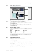
Fig. 4-6
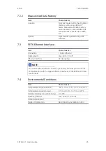
Equivalent Circuitry of the ECU JTAG/ LFAST Interface (ECU)
4.7.1
Layout Recommendation for LFAST Mode
The wires /TRST, TDO should be closed together, with the same length, single
ended impedance 50Ohm.
The wires TMS, TDI should be closed together, with the same length, single
ended impedance 50Ohm
4.7.2
Debugger and MC Support
The FETK-S2.1 supports the JTAG mode for XCP debugger arbitration, test and
calibration.
For LFAST mode the FETK-S2.1 starts at first in JTAG mode to switch into
LFAST mode automatically.
4.8
Trigger Modes: Overview
The FETK-S2.1 supports the following trigger modes:
• Pinless triggering
• Timer triggering
The trigger mode "Pinless Triggering" uses the microcontroller’s internal Devel-
opment Trigger Semaphore (DTS) for triggering. See also chapter “Pinless Trig-
gering” on page 25.
The trigger mode "Timer Triggering" uses four internal timers of the FETK for
triggering. See also chapter “Timer Triggering” on page 26.
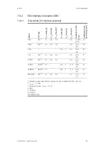
Mode
Debugger support
MC support
JTAG
Yes
Yes
LFAST
No
Yes
FETK
ETAM8
ETAM2
ECU
/TRST
TMS
>=
10
0k
Ubatt1
CAL WAKEUP (12V)
GND
TDO
GND
/PORST
VDD
(Sense)
TCK
ESR0,
/HDRST
1
2
9
10
V
DDS
R
A
M
TDI
supply
and
monitor
the
voltage
of
the
ED
RAM
/WGDIS
circuit
/PORST
VDDSTBY
(1,3V)
VDDPSTBY
(3,3V)
6
optional
VDD
Ubatt2
If
there
is
a
resistor
connected
to
pin
/TRST
it
should
be
a
pulldown
>=
100
kOhm
MPC57xx
JTAG_Mode:
DRCLK_ECU
TXD_ECU
‐
RXD_ECU
‐
LFAST_Mode:
DRCLK
TCK
TXD
‐
TDI
RXD+
TDO
RXD
‐
/TRST
/WGDIS
TXD+
TMS
/RSTOUT
1
Ubatt 1: Permanent power supply
(ECU internal or external)
If permanent power supply is external ,
connect to an additional ECU internal
voltage
Ubatt 2:


