


Installation
CAN bus installation
9
•
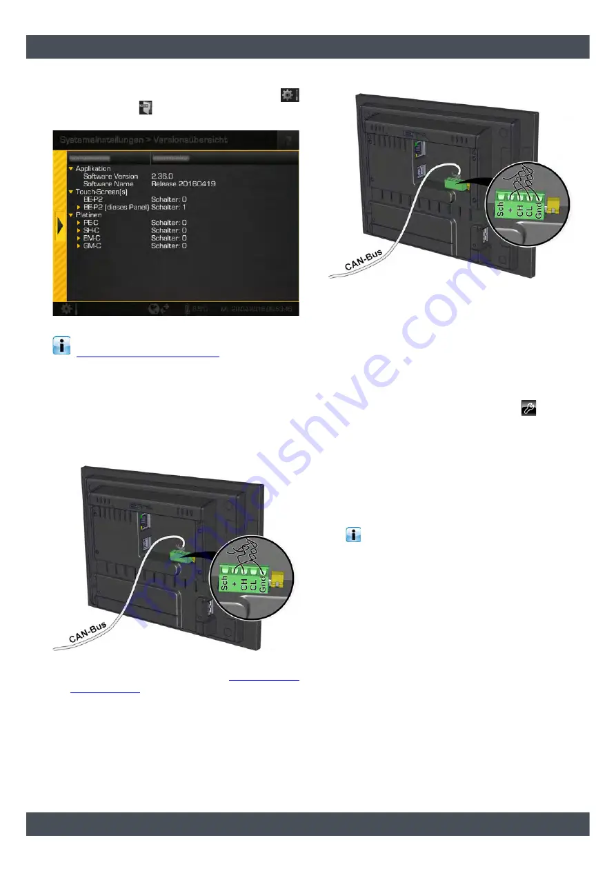
Software version X.36.0 and later
On the control panel, open the system settings
and press the
[Version overview] button. The
node number set is displayed in the overview.
Fig. 2-3: Overview (from X.36.0)
Setting the node number is described in chapter
2.3.1.1 "Setting node numbers"
.
Increasing the node number of the control panel
The node number is set to "1" by default. If a control
panel is already available with node number "1", this
must be increased for the new control panel.
1. Switch off the entire heating system.
2. Detach the CAN-Low (CL) wire.
3. Switch on the entire heating system.
4. Set the node number (see chapter
)
5. Switch off the entire heating system once again.
6. Reattach the CAN-Low (CL) wire.
7. Restart the entire heating system. The change will
only take effect after restarting.
2.3.1.1
Setting node numbers
Up to software version X.35.X
Set node number on ETAtouch control panel
1) Switch on the entire heating system.
2) On the ETAtouch control panel, press
.
3) Press [Change authorisation].
4) Raise the access level to [Service].
5) Press [System configuration].
A window with the system settings appears.
6) Press the [Change] button next to [CAN node
switch].
A window appears where you can enter the
desired node number.
The values 0 to 7 are permitted for the node
numbers.
7) Press [Accept].
8) Restart the entire heating system.
The change will only take effect after the restart.
Software version X.36.0 and later
Set node number on ETAtouch control panel
1. Switch on the entire heating system.
2. On the ETAtouch control panel, increase the au-
thorization level to [Service].


