background image

21

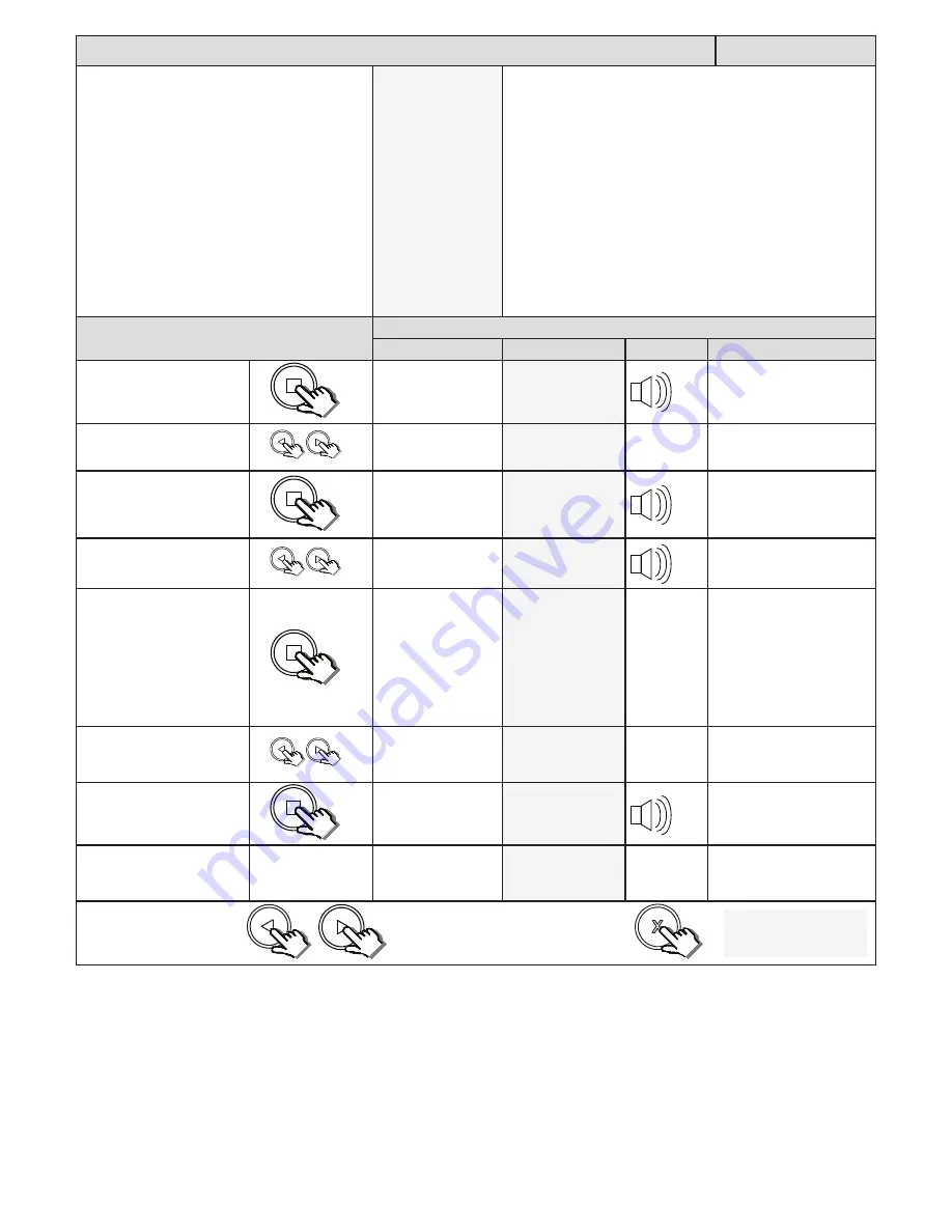
Setting up the pedestrian open distance and pedestrian auto-close time.

Ped Setting

From Standby status

- “Selected” mode -

                  - Standby

NB! The runtime setup must be completed first before the 

pedestrian setup can be attempted.

The factory default pedestrian opening is 1 meter.

The factory default auto-close time is 2 seconds. The timer 

range is 1 – 254 seconds.

PLEASE  NOTE!!  If  no  safety  beams  are  installed  then  the 

pedestrian  mode  reverts  to  4  step  mode  where  the  gate 

will  not  auto-close.  A  set  of  safety  infra-red  beams  must 

be installed using the technique indicated in this manual to 

allow for auto-closing in pedestrian mode. The safety beam 

function  on  this  control  card  conforms  to  the  CE  safety 

standards.

Action

Response

Description

Display

Buzzer

Gate

To enter the program menu. 

Press and hold the 

 button 

until buzzer beeps.

Display and buzzer 

confirms.

Programming menu

<or> for options

Scroll < or > to select the 

pedestrian setting option.

Display scrolls 

through options.

Ped Mode Setting

<     

  = change    >

With “Ped Setting” on the 

display, press and release 

.

Display shows current  

pedestrian opening 

distance.

Pedestrian open 

distance: 1000mm

Scroll < or > to the required 

setting.

Display changes 

respectively.

Pedestrian open 

distance: 1200mm

With required setting 

displayed, press and release 

.

Display briefly shows 

the new setting 

is saved and then 

prompts you to set 

the pedestrian auto-

close time if safety 

beams have been 

installed and setup 

correctly.

Pedestrian Setting

Auto-close = 5s

Scroll < or > to the required 

setting if necessary.

Display changes in 

seconds with each 

button press.

Pedestrian Setting

Auto-close = 3s

With required setting 

displayed, press and release 

.

Display briefly shows 

the new setting is 

saved.

Pedestrian Setting

Saved = 3s

After display confirms new 

setting.

Beam Setup

Enabled Saved 

Display returns to 

programming menu 

options list.

Beam Setup

<    


  = change    >

x2

x1

x1

x2

Scroll left or right to next 

program option.

OR

“Selected” mode

- Standby

EXIT back to standby 

status

Summary of Contents for DRIVE 1000

Page 1: ...ET DRIVE1000 INSTALLER 2016 001 003 Installer Instructions High Traffic 1000kg Slide Gate Operator www et co za...

Page 2: ...e Page 22 Receiver programming and setup Page 29 Advance programming options and their definitions Operating mode definitions and examples Page 31 Collision sensing and safety overload routines Page 3...

Page 3: ...ns of mechanical ends of travel stoppers 5 Ensure all fixed mounting points such as the wall above the door in a garage door system or the posts in a swing gate system are sound and strong enough to a...

Page 4: ...d in at a battery merchant for safe disposal Before removing the battery from the system the household mains must be disconnected In the case of the motor unit being removed and scrapped the battery m...

Page 5: ...put 3 Plug in terminal connectors 12 Manual override access hatch 4 ACDC power pack 13 Manual override access hatch lock 5 Battery 14 Electric motor 6 Levelling and height adjusting bolts 15 Electric...

Page 6: ...ad in nylon be used The guidance system should be installed at the top edge of the gate whenever possible In cases where this is not possible the guidance system should never be below the halfway poin...

Page 7: ...Rolling Resistance Max Duty Cycle Drive 1000 ACDC option 1000 kg 40 kgf 30 kgf 98 Drive 1000 Battery dependent option 1000 kg 40 kgf 30 kgf 25 Where to position the gate motor Liquid ingress The ET D...

Page 8: ...there 1 29V 3 Alarm panel 2 11 4 10 8 9 1 6 5 7 1 Courtesy lights twin earth 1 0mm back to motor housing and isolator switch 7 Free exit loop 1 5mm silicone insulated single core flexible stranded ca...

Page 9: ...he concrete must cure properly before continuing with the installation Whichever mounting method you opt for the position of the base plate will always remain the same Here are the dimensions to use w...

Page 10: ...2 Unlock and open the manual override hatch 3 Lift the main cover to remove it Mounting the gearbox You will need a 13mm socket or spanner and a 5mm Allen hex key The gearbox is fastened onto the base...

Page 11: ...the manual override hatch closed and locked up To disengage the gearbox Manual mode 1 Raise lock cover 2 Insert the key 3 Turn the key clockwise 4 Open the manual override hatch 5 Swing manual overrid...

Page 12: ...he wheel shrinkage will cause the gate to sit heavier on the pinion or when the rack is no longer square to the pinion due to gate flex False safety sensing activation The following shows a simple met...

Page 13: ...closed until the next length of rack meets the first length and the opposite end once again rests on the pinion To ensure the 2 lengths of rack marry correctly use an off cut of rack clamped upside do...

Page 14: ...C O C certificate of compliance by a registered electrician In the case of the plug in transformer being used where the low voltage 29Vac is run to the gate there is no need for the all pole isolator...

Page 15: ...0 Safety beam RX Com N C N O N O N O Loop detector Non polarity sensitive termination for 2 wire Bluebus devices For example safety beams 24V 5Ah Battery Standard in kit Optional 24V 3 5Ah Battery 24V...

Page 16: ...0 machine bolt upside down on top of the spine of the rack in line with the limit switch 3 Fasten the actuator down onto the rack using either the M4 x 20mm self tapping screw supplied with the kit or...

Page 17: ...t all the way back to standby without saving when in programming Enter programming advance to next level of option on display save value on display Control card programming and setup 1 Runtime setup P...

Page 18: ...s reached and the closed limit is triggered LED on Gate stops and starts opening Display prompts you to stop the gate in the open position Learning length Press at open Press and release the button to...

Page 19: ...to programming menu options list Overload Setting change x2 x1 x1 Scroll left or right to next program option OR Selected mode Standby EXIT back to standby status x2 Safety infra red beams setup Beam...

Page 20: ...Setting on the display press and release Display shows current option status BT Mode Setting Standard Scroll or to the required BT mode option Display changes respectively BT Mode Setting Standard BT...

Page 21: ...ions Scroll or to select the pedestrian setting option Display scrolls through options Ped Mode Setting change With Ped Setting on the display press and release Display shows current pedestrian openin...

Page 22: ...ceiver Setup Quick learn With Quick learn on the display press and release Display prompts you to select a function Select function BT Full opening Scroll or to the required receiver function channel...

Page 23: ...and hold any button on the remote transmitter All four buttons must be set to the same format for this to work in the same way as this example While still transmitting with the remote button press an...

Page 24: ...splay press and release Display prompts you to select an available user address Select address 1 used Scroll or to select an available user address Display changes respectively Select address 2 With a...

Page 25: ...display press and release Display shows first erase option Erase Remotes Select Address With Select Address on the display press and release Processor scans the memory and then displays the first avai...

Page 26: ...Scroll or to select the Erase ALL memory option Display scrolls through options Erase Remotes Erase ALL memory With Erase ALL memory on the display press and release Display then prompts you to press...

Page 27: ...release Display prompts you to press and release a remote button Diagnose Remotes Press Remote After prompt Display shows a signal strength graph and waits for a remote transmission Signal Not recogni...

Page 28: ...splay press and release Display shows receiver setup options Receiver Setup Quick learn Scroll or to select the Receiver info option Display changes respectively Receiver Setup Receiver info With Rece...

Page 29: ...timising the external battery and charger s performance AC monitoring This option allows you to disable the Vac mains failure monitoring on sites where a solar panel system has been installed to maint...

Page 30: ...troller settings to the last saved restore point Clear logs Use this feature to clear the event fault and trigger logs NB this does not clear the cycle counter Factory reset Use this feature to defaul...

Page 31: ...es with a pedestrian for example Gate stops opening Once gate has stopped Gate reverses momentarily to release pressure No buzzer tones After reversing momentarily Gate stops and waits for next trigge...

Page 32: ...r next trigger to close No buzzer tone Momentary BT trigger Gate begins closing No buzzer tone User manual reference Page 7 Safety infra red beams function All modes except P I R A C Basic operating f...

Page 33: ...to each BT trigger In Standard mode you have access to the following advanced features Holiday lock out and Party mode Action Response Momentary BT trigger Gate begins opening No buzzer tones At full...

Page 34: ...rty mode NB For any auto close feature to work a pair of safety infra red beams must be installed and functioning correctly If no safety infra red beams are installed then the gates will open but not...

Page 35: ...ng correctly If no safety infra red beams are installed then the gates will open but not close again Action Response Momentary BT trigger Gate begins opening No buzzer tones Momentary BT trigger while...

Page 36: ...ty infra red beams must be installed and functioning correctly If no safety infra red beams are installed then the gates will open but not close again Action Response Momentary BT trigger Gate begins...

Page 37: ...trian transaction is cancelled The system then reverts to either the Loop or BT trigger mode depending on which was triggered There are two ways of activating the PED functions on this control card Ei...

Page 38: ...he Loop or BT trigger mode depending on which was triggered There are two ways of activating the PED functions on this control card Either via the hardwired PED input or the PED receiver channel Actio...

Page 39: ...not close again Action Response Loop trigger Gate begins opening No buzzer tones Momentary BT trigger or Loop trigger while gate is opening The trigger is ignored and the gate continues opening No bu...

Page 40: ...d battery of the control unit Below is an example of strike lock mode when standard BT mode is active Action Response Momentary BT trigger Auxiliary relay activates No buzzer tone Half a second after...

Page 41: ...an damage the charger and battery of the control unit Below is an example of magnetic lock mode when standard BT mode is active Action Response Momentary BT trigger Auxiliary relay activates No buzzer...

Page 42: ...e Action Response Momentary BT trigger Auxiliary relay activates No buzzer tone Gate begins opening Gate reaches open position Gate stops No buzzer tone Momentary BT trigger Gate begins closing No buz...

Page 43: ...y Relay receiver function is pressed and released Latch mode The transmitter must be released and pressed again to reactivate the relay each time Action Response Momentary relay trigger Auxiliary rela...

Page 44: ...esponse Momentary BT trigger Gate begins opening No buzzer tones At full open position Gate stops No buzzer tones Momentary BT trigger Gate begins closing No buzzer tones Momentary BT trigger Gate sto...

Page 45: ...Response Momentary trigger from any transmitter button programmed into holiday lock out function Buzzer begins toning and status LED comes on BT button while buzzer is sounding to confirm that you wa...

Page 46: ...ction Buzzer begins toning and status LED comes on BT button while buzzer is sounding to confirm that you want to activate holiday lock out If no BT button is pressed during this 5 second window the a...

Page 47: ...armed response standby point or to the nearest police station This way they can ask for an escort onto the property Safety beam alarm mode is available in all modes of operation so long as a set of sa...

Page 48: ...abled On Off Status LED indications and buzzer guide Description Visual confirmation Buzzer Reason Static off None Gate fully closed Flashing slow 1 second on and 1 second off None Gate running normal...

Page 49: ...ent charger stage Bat Curr limit Battery charger status Charger is in current limiting Battery is level is low or there is a battery wiring fault Bat Err FET shrt Battery charger status The charger FE...

Page 50: ...ed as this is not monitored Not IEC compliant Beam Test Monitored LF N C Low frequency switched beam monitoring with Normally closed contacts wiring detected High safety option IEC compliant Beam Test...

Page 51: ...d when changing parameters that affect how the gate runs and hence the overload sensing Holiday Locked Holiday Lockout enabled Deactivate as per page 43 IEC Mode Error No Beams IEC mode has been enabl...

Page 52: ...pen on a pedestrian trigger Page 21 Power error braking Device is about to shut down due to low power motor is slowing down Low AC PSU and Bat voltages Power error resetting Device is about to shut do...

Page 53: ...zed non manufacturer modifications to the product or components thereof 2 Any modification to the installation methods described in the installation instructions 3 Any application or use of the produc...

Reviews: