16
Installing the limit actuator.
RELEASE
LIMIT L
LIMIT R
BLUEBUS
BT
GND
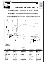
This diagram depicts how to install the limit actuator.
1.
Push the gate up against the closed stopper.
2. Remove the rack screw (holding the nylon teeth to the steel angle) closest to being in line with the limit switch. Or in the case of steel rack, weld a
M4 x 20 machine bolt upside down on top of the spine of the rack in line with the limit switch.
3. Fasten the actuator down onto the rack using either the M4 x 20mm self-tapping screw supplied with the kit or with a nut in the case of steel rack.
4. Adjust the actuator so that it is approximately halfway across the limit switch.
5. Move the gate open and then closed again. Ensure the limit LED comes on before the gate impacts with the closed stopper. Positive closed mode
will always close the gate the last 50mm if selected in programming.


