Vertical flail unit VS-122
The illustrations, descriptions and data contained in these Instructions are limited to important details and are only partially binding. The Manufacturer reserves the right, at any time and furthermore
without notification, to undertake modifications which contribute to the technical improvement of the product.
ESM # 902.0976 EN
Blade carrier, knife driving shaft and their bearings
•
A bent or badly damaged blade carrier (Figure 1/e) must be replaced. Welded repairs on the blade carrier are expressly forbidden!
•
Check fixing bolt (Figure 1/f) on the blade carrier regularly!
o
For blade carriers whose working direction is to the left, the fixing bolt (Figure 1/f) has a right-hand thread!
o
For blade carriers whose working direction is to the right, the fixing bolt (Figure 1/f) has a left-hand thread!
Replacing the blade carrier is carried out from the underside of the cutter unit. (Prior to this, turn the vertical flail unit over or secure in a raised position).
To replace:
1.
Loosen fixing bolt (Figure 1/f) and replace blade carrier.
2.
Lay the washer (Figure 1/h) so that its chamfer faces away from the blade carrier.
3.
Then lay the thrust washer on top and tighten the bolt (Figure 1/f) to 180Nm.
•
The knife driving shaft (Figure 1/i) and its bearings should be checked regularly for functional safety. Replace damaged knife driving shafts and/ or
bearings immediately.
•
Grease blade shaft bearings on a daily basis (see lubrication schedule).
Cutter unit enclosure and eject protector
The cutter unit housing and the eject protector (front/rear) must always be checked for operational safety. Loose, deformed, or damaged components
must be tightened, replaced, or repaired immediately.
In the event of damage, the eject protector is to be replaced with an ESM Original Spare Part immediately.
Blade brake
All vertical flail units of the angular gear type are provided with blade brakes as standard. In the case of special models and models with belt drive,
without blade brake, it is the responsibility of the manufacturer / the distributor of the implement carrier to comply with the specified blade run-down
time.
•
Carry out a function check every 100 operation hours, but at least once a year. The blade run-down time (time after disconnecting the drive
mechanism until the blade carrier stops) must be less than/equal to 7 seconds! In the event that the required run-down time is exceeded, the brake
must be readjusted as described below.
•
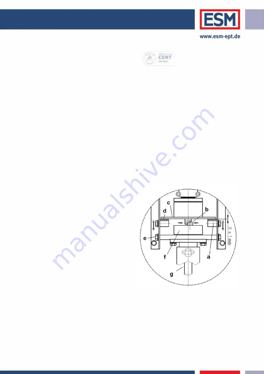
Worn brake pads (a) must be replaced!
1.
Remove the top cover plate on the drive housing. Turn the driving disk (f)
with its engaging bolts against the ramp bolts on the hub facing the
gearbox (b). Pull the engaging bolts onto the chamfer of the ramp bolts as
far as they will go by applying lock-grip pliers and lock the pliers.
2.
Now loosen the 4 bolts (e), which fasten the brake pads (a) against the side
panels sufficiently that the brake pads (a) can be slid into position by
hand.
3.
Place a feeler gauge between the brake lining (d) and brake disc (c)
(X=1mm thickness).
4.
Push the brake pad (a) evenly both top and bottom against the feeler
gauge and tighten the bolts (e) on the exterior of the side panel again.
Loosen the lock-grip pliers and remove. Put the protective cover back
again.


