


630288_0_Manual_Installation-Service_ST900_AUS NZ
18
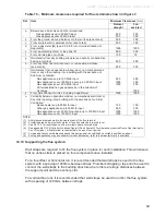
Table 16
–
Minimum clearances required for flue terminals shown in figure 3
Ref.
Item
Minimum Clearances
(mm)
Natural
draught
Fan
assisted
a
Below eaves, balconies and other projections:
Gas appliances up to 50 MJ/h input
Gas appliances over 50 MJ/h input
300
500
200
300
b
From the ground, above a balcony or other surface (see note 6)
300
300
c
From a return wall or external corner (see note 6)
500
300
d
From a gas meter (M) (see 2.5.4.9 for vent terminal location of
Regulator)
1000
1000
e
From an electricity meter or fuse box (P)
500
500
f
From a drain pipe or soil pipe
150
75
g
Horizontally from any building structure (see note 6) or obstruction
Facing a terminal
500
500
h
From any other flue terminal, cowl, or combustion air intake
(see note 6)
500
300
j
Horizontally from an openable window, door, non-mechanical air
Inlet, or any other opening into a building with the exception of
Sub-floor ventilation:
Gas appliances up to 150 MJ/h input
Gas appliances over 150 MJ/h input up to 200 MJ/h input
Gas appliances over 200 MJ/h input
All fan-assisted flue gas appliances, in the direction of
discharge
500
1500
1500
300
300
500
1500
k
From a mechanical air inlet, including a spa blower
1500
1000
n
Vertically below an openable window, non-mechanical air inlet, or
Any other opening into a building with the exception of sub-floor
Ventilation:
Space heaters up to 50 MJ/h input
Other gas appliances up to 50 MJ/h input
Gas appliances over 50 MJ/h input and up to 150 MJ/h input
Gas appliances over 150 MJ/h input
150
500
1000
1500
150
500
1000
1500
NOTE-
(1) All distances are measured to the nearest part of the flue terminal
(2) Prohibited area below electricity meter or fuse box extends to ground level
(3) See 2.6.13.3 for restrictions on a flue terminal under a covered area
(4) See appendix G LPG Cylinder Locations, figure G2 and figure G3, for clearances required from a flue terminal to
An LPG cylinder. A flue terminal is considered to be a source of ignition.
(5) For gas appliances not addressed above, the design shall be certified by a suitably qualified engineer.
(6) Some gas appliances may be suitable for closer installation; refer to the manufacturer’s instructions.
12.10 Supporting the flue system:
Wall straps are required to fix the flue system in place for each installation. This will ensure
that no undue strain is placed on flue components once installed.
For a flue offset or horizontal run, it is recommended that wall straps be used to the flue
system with a spacing of 900mm between straps. Plumbers strapping / tape can be used to
connect the wall straps to the building structure where there are large distances between
the support point and the anchor point.
For vertical flue runs it is recommended that wall straps be used to anchor the flue system
with a spacing of 1200mm between straps.


