


630288_0_Manual_Installation-Service_ST900_AUS NZ
12
280.0
280.0
174.8
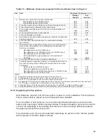
Ø265mm hole required in
wall to fit wall thimble
317mm
317mm
200mm max-
120mm min
Optional Wall Thimble
12.0
Installing the Flue System:
Ensure all flue components are Simpson Duravent Direct Vent Pro 5” x 8,” no other flue
types may be used.
Note:
Consult section 12.13 to ensure correct length of flue is calculated.
There are two basic types of Balanced Flue System installations:
• Horizontal Termination
•
Vertical Termination
Use the diagrams in sections 12.5, 12.6 & 12.7 to check if your proposed flue system is
acceptable. Section 12.9 will also need to be used to determine whether the flue terminal
location meets the requirements of AS/NZS 5601. Then use Appendix A to work out the
quantities of the flue components that are required.
12.1
Any offsets in your flue configuration should be 45
°
where possible
.
12.2
If your flue configuration has a horizontal run, there must be a minimum 1
°
inclination
(20mm vertical rise per 1m horizontal run) leading upwards towards the termination.
Do not install the flue with horizontal sections sloping down towards the termination.
This could cause the fire to operate incorrectly and possibly create an unsafe
condition.
12.3
The flue must maintain the
following clearances to
combustible materials;
25mm from all sides and
bottom of the flue, and
50mm from the top of
the
flue.
12.4
If your flue configuration falls
on or near a restriction zone
boundary line in diagrams
12.5, 12.6 & 12.7, it may
require the restriction value
from either side of the
boundary line to achieve the
correct flame aesthetic, this
may vary from installation to
installation.
Ø203mm


