background image

9  Control Terminal T

ergoselect  4 / 5


59

Interval HR

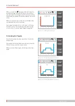
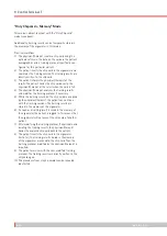
For HR-controlled interval training protocols it is possible 
to define an automatic adaptation of the load levels to take 
place during the training sessions.

The criteria for monitoring of the heart rate are a defined 
upper and a lower heart rate limit. The limit is the sum of 
the training heart rate (Trng. HR) and the "Threshold".

•  Upper Limit  = Trng. HR + Threshold
•  Lower Limit  = Trng. HR - Threshold

If the measured heart rate is permanently above the upper 
training heart rate limit at the falling edge of an interval 
for a certain period of time (parameter "Delay"), the load 
for the subsequent training interval will be reduced.

If the measured heart rate is permanently below the lower 
training heart rate limit at the falling edge of an interval 
for a certain period of time (parameter "Delay"), the load 
for the subsequent training interval will be increased. 
A load increase, however, is only possible when the load 
was reduced before, because the load specified for the train-
ing interval is always the maximum possible training load.

The entered heart rate should be determined individually 
for each patient.

(See also section “HR Monitoring” on page 77).

Warning


  Patient Hazard

Heart rate measuring systems may be inaccurate. 
Incorrect and/or prohibited use and/or over­ex­
ercising may have serious or even fatal conse­

quences. The training has to be stopped immediately if the test 
subject experiences symptoms like dizziness.

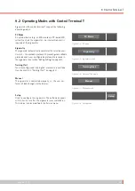
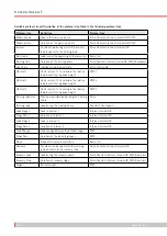
 2.

Description

Type

Warm-Up Load

Warm-Up Time

Interval HR

Interval HR 

20 W

2 min

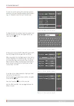
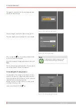
Figure 9 – 36:  Protocol type "Interval HR" – level 1

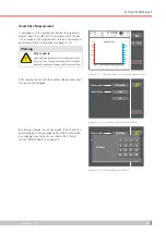
 1.


 3.

Training Time 

20 min

Heart Rate 

100 1/min

Recovery Load 

20 W

Recovery Time 

3 min

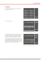
Figure 9 – 37:  Protocol type "Interval HR" – level 2

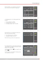
 2.


Load Stage 1 

50 W

Stage Time 1 

30 sec

Load Stage 2 

5 W

Stage Time 2 

60 sec

Figure 9 – 38:  Protocol type "Interval HR" – level 3


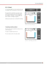
W

200

150

100

50

0

10 

15 

20 

25

1/min

200

150

100

50

0


76

1/min

98

%

15:00

mm:ss

65

1/min

25

W

mmHg

118/96

End

const.

Stop

– 5 W

+ 5 W

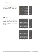
Figure 9 – 39:  Example of an interval HR training

Summary of Contents for ergoselect 4

Page 1: ...ergoselect 4 5 Ergometer Operator s Manual 201000433000 Version 2021 06 01 Rev 04 English...

Page 2: ......

Page 3: ...ction is acknowledged No part of this manual may be reprinted translated or reproduced without the manufactur er s written permission This manual will not be automatically updated Please contact the m...

Page 4: ...Cuff 15 4 10 Connecting the SpO2 Sensor 16 5 Applied Parts 17 5 1 ECG 17 5 1 1 Contraindications 17 5 1 2 Intended Purpose 17 5 1 3 Safety Information 17 5 1 4 Disposable Electrodes 18 5 1 5 Suction...

Page 5: ...tem On 33 7 2 Operating Mode with Control Terminal M 33 8 Control Terminal P 35 8 1 Turning the System On 35 8 2 Operating Modes with Control Terminal P 36 8 2 1 PC Mode 36 8 2 2 Ergometry 37 8 2 3 Ma...

Page 6: ...meter 84 13 2 Blood Pressure Module Option B 86 13 3 SpO2 Module Option S 86 13 4 ECG Module Option A 87 13 5 Exercise Test Protocols 87 13 7 Test Protocols control terminal T only 88 13 8 Family of c...

Page 7: ...mbly maintenance inspection and repair of the device must read and understand the content of this manual before using the device or working with it Paragraphs with special symbols are of particular im...

Page 8: ...g Shock Hazard When the device is connected to other equip ment or if a medical system is created it must be ensured that the added leakage currents do not present a hazard In case of questions please...

Page 9: ...f ventricular tachycardia new atrial fibrillation or supraventricular tachycardia development of new bundle branch block progression of heart block to second or third degree cardiac arrest Clinical cr...

Page 10: ...ho judged them to be suitable for the appli cation described in the intended use 2 5 Biocompatibility The parts of the product described in this manual includ ing all accessories that come in contact...

Page 11: ...inspection e g March 2022 Toggle switch ON voltage Toggle switch OFF voltage Button to adjust the handlebar height r Handlebar UP Toggle switch OFF s Handlebar DOWN CE mark per the Medical Device Dir...

Page 12: ...gle switch I 0 10 Saddle adjustment with clamping lever 1 2 3 4 5 6 7 8 9 10 Figure 4 1 ergoselect 4M 1 Control terminal T 2 Speed readout for patient 3 Connectors e g for blood pressure cuff SpO2 4 A...

Page 13: ...hen you have reached the new location lower the ergometer very carefully to protect it from considerable damage Caution Equipment Damage Avoid strong vibrations of the ergometer during transport Figur...

Page 14: ...r is allowed to change the orientation of the control terminal If the control terminal is mounted inappropriately the tubing and cables may be bent or damaged The device will only operate correctly if...

Page 15: ...8 Assembly position Caution Equipment Damage Before connecting the ergometer to the power line check that the line voltage corresponds to the ratings on the type plate The type plate is located on the...

Page 16: ...ort different communication modes digital analog remote start etc All ergometers are equipped with a digital interface Spe cial adapters are needed for analog control or the remote start capability Pl...

Page 17: ...the intended port 1 so that it clicks into place Slip the cuff tubing onto the fitting 2 and engage To disconnect push back the connector s knurled sleeve Artifacts must be avoided while the blood pre...

Page 18: ...application and use check the SpO2 sensor and its package for damage Do not use the sensor if you detect any signs of damage Connect the sensor cable to the corresponding socket 1 on the underside of...

Page 19: ...electrocar diographic monitoring of critical care patients No pacemaker detection There is a risk of inadequate therapy and or over exertion The ECG module may continue to count the pacemaker rate dur...

Page 20: ...or the patient In the case of patients with medical conditions such as arterial occlusive disease or severe blood coagulation disease the physician must decide whether or not to use the device R L N 1...

Page 21: ...ns The BP module is not intended for use in ICUs or ambu lances The BP module is not intended for neonates or pregnant women The BP module may not be used simultaneously with HF surgical devices The B...

Page 22: ...exceeds 320 mmHg You can check the proper functioning of this safety precau tion by abruptly bending your arm while the cuff is being inflated causing a brief overpressure in the cuff The cuff must de...

Page 23: ...k that the metal clasp 1 is inside the marked index range 2 and not outside 1 2 Figure 5 4 Wrong cuff size Caution A cuff not directly applied on intact skin can cause incorrect measurements Be sure t...

Page 24: ...ies the position of the microphone The accurate placement of the microphone is the primary condition for reliable pressure measurement during exer cise tests The cuff must be applied directly on the s...

Page 25: ...he patient If by accident an excessive pressure builds up inside the cuff either remove the cuff immediately from the arm or discon nect the cuff tubing from the control terminal The same measures are...

Page 26: ...w hemoglobin concentrations arterial dyes artificial fingernails and dark nail polish The SpO2 module is not designed for operation in the vicinity of MRT NMRI or X ray systems and may not be used in...

Page 27: ...hand Within a few seconds the current oxygen saturation in percent will be indicated on the display Caution Do not apply the SpO2 sensor to the same arm as the blood pressure cuff You may obtain incor...

Page 28: ...r according to the manufacturer s instructions Figure 5 10 Applying the standard SpO2 sensor example Figure 5 11 Applying the standard SpO2 sensor example 5 3 6 Applying the Ear Sensor Apply the ear s...

Page 29: ...are therefore not capable of using rehabilitation facilities 5 4 2 Intended Purpose The heart rate module is a device for acquisition calcula tion and transmission of the patient s heart rate It is u...

Page 30: ...en the electrode surfaces grooved area on the inside with electrode gel or spray 1 1 2 3 4 5 2 3 5 3 4 Transmitter unit Webbing chest strap Electrodes Fastening mechanism Adjustment belt 1 3 4 5 3 4 5...

Page 31: ...snugly Check that the moistened marked areas are flat against the skin and that the text on the heart rate sensor has the correct orientation and is positioned in the middle of the chest For further i...

Page 32: ...ut 1 speed low patient should pedal faster 2 correct speed 3 speed high patient should pedal more slowly Note If during an exercise test the speed drops below 30 RPM the load reading starts blinking o...

Page 33: ...ontrolled via the toggle switch on the handlebar Figure 6 3 Toggle switch for adjusting the height of the handlebar 6 3 Saddle Adjustment 6 3 1 Motor Assisted Saddle Adjustment On the different ergome...

Page 34: ...ping lever Danger With the ergometer standing firmly check that the saddle is securely clamped by trying to push it downwards from above Adjust the clamping force of the clamping lever if necessary 6...

Page 35: ...e ergometer has been turned on and the self test completed Control terminal M is entirely operated by remote control e g from an ECG recorder or a PC With this key you initiate a blood pressure measur...

Page 36: ...be terminated with the corre sponding command from the controlling ECG unit 120 Watt 15 min 76 138 96 mmHg 122 min min 1 2 3 4 5 6 Figure 7 4 Exercise test screen 1 1 current load watts 2 most recent...

Page 37: ...be configured to default to one of the operating modes If this option is selected the start screen of the selected operating mode e g Ergometry will be displayed instead of the main menu With the key...

Page 38: ...re user configurable and stored in the system see chapter 8 2 4 Settings with Control Terminal P on page 40 Manual The ergometer is controlled manually i e the user per forms all load changes via the...

Page 39: ...ndicating wireless connection Bluetooth or WLAN 4 duration of exercise test min 5 heart rate measurement with the ergoline digital chest strap 6 heart rate at the time of the BP measurement BPM 7 peda...

Page 40: ...st protocol The exercise test is started with the Start key a blood pressure measurement at rest may precede the test depending on the selected exercise test protocol When the basic load appears on th...

Page 41: ...the user controls the entire exercise test by selecting the loads stage times and by initiating blood pressure measurements PC Mode Ergometry Manual Settings Select Figure 8 13 Main menu The exercise...

Page 42: ...ain menu Use the softkeys on the right and left to position the bar cursor on the parameter to change and confirm the selection with Select Settings Default Mode Protocols Contrast Load Change Languag...

Page 43: ...it At Select for example you can choose the protocol type Step load increase in steps or Ramp continuous load increase Press Select to save the selected protocol type To cancel the selection press the...

Page 44: ...ual load changes Language The texts can be displayed in different languages Select Language Deutsch English Fran ais Espa ol Italiano Figure 8 25 Language menu Beep The audio signal emitted during blo...

Page 45: ...09 00 00 Date Time Select Figure 8 28 Setting the date 30 06 2021 09 00 00 Date Time Select Figure 8 29 Setting the day ECG Type The selected ECG Type determines the communication method with the ECG...

Page 46: ...Select the communication mode and confirm with Select ECG Type Analog with pulse Analog Digital Digital Analog IN OUT Select Figure 8 31 Selecting the ergometer communication mode Note The ECG Type n...

Page 47: ...ect wears a chest strap to measure the heart rate during the training the corresponding chest strap number must be entered here You will find the number on the back of the housing It is the unique ide...

Page 48: ...the ergometer has been turned on and the self test completed The device can be configured to default to one of the operating modes If this option is selected the start screen of the selected operatin...

Page 49: ...ed editable protocols and 5 user configurable protocols are saved in the ergometer see section Editing Settings on page 50 Ergometry Figure 9 5 Ergometry mode Training Test Ten user configurable train...

Page 50: ...nt will stop the measurement 16 W 200 150 100 50 0 0 5 10 15 20 25 1 min 200 150 100 50 0 0 1 min 0 00 00 mm ss 0 1 min 0 W mmHg 2 1 3 4 5 7 6 ECG RR Waiting for start Saddle Figure 9 9 PC mode screen...

Page 51: ...0 5 10 15 20 25 1 min 200 150 100 50 0 0 1 min 0 00 00 mm ss 0 1 min 0 W mmHg RR Waiting for start Figure 9 11 PC mode screen with assigned heart rate belt After tapping the key with the number 16 an...

Page 52: ...9 14 Ergometry menu Editing Settings When you touch a protocol the available parameters will be displayed All protocols can be edited during operation except for the PC mode User configured custom pr...

Page 53: ...2 key you proceed to the next menu level where you can edit these parameters the recovery load from 6 to 100 W and the recovery time from 1 to 30 min With the 1 key you return to the previous screen 1...

Page 54: ...5 1 min 200 150 100 50 0 0 1 min 0 00 00 mm ss 0 1 min 0 W mmHg Waiting for start const Start 5 W 5 W Figure 9 20 Starting an exercise test Terminating the Program Once the full protocol has been comp...

Page 55: ...vidual patient Training Test All displayed protocols are editable before the protocol is started Definitions A training session pulse constant interval interval HR is defined by the phases Warmup Trai...

Page 56: ...to calculate the relative load in watts per kg body weight PWC 2 HR Limit 3 Heart rate limit 3 to calculate the relative load in watts per kg body weight PWC 3 Training load max Maximum possible load...

Page 57: ...lable Polar Note Make sure that the selected belt ID is the ID of the belt actually used on the patient Further editing options depend on the selected protocol type they are described in detail for ea...

Page 58: ...ption Heart Rate Type Warmup Load Warmup Time Pulse Belt 2 Pulse 20 W 2 min Figure 9 26 Protocol type Pulse level 1 Warning Patient Hazard Heart rate measuring systems may be inaccurate There is a ris...

Page 59: ...Up Time 2 min Description Constant Figure 9 29 Protocol type Constant level 1 1 Training Time 20 min Training Load 50 W Recovery Load 20 W Recovery Time 3 min Figure 9 30 Protocol type Constant level...

Page 60: ...Protocol type Interval level 1 1 3 Training Time 20 min Recovery Load 20 W Recovery Time 3 min Figure 9 33 Protocol type Interval level 2 2 Load Stage 1 50 W Stage Time 1 30 sec Load Stage 2 5 W Stage...

Page 61: ...se however is only possible when the load was reduced before because the load specified for the train ing interval is always the maximum possible training load The entered heart rate should be determi...

Page 62: ...n be adjusted manually also after the session was started The training stops automatically when the timer runs out Description Countdown Heart Rate Belt 2 Type Countdown Recovery Time 6 min Recovery L...

Page 63: ...results must be verified and evaluated by a qualified physician to obtain a diagnosis and set up a therapy plan 2 Description Ramptest Heart Rate Belt 2 Type Ramptest Basic Load 20 W Slope 25 W min Fi...

Page 64: ...on the defined heart rate limits in the protocol type To correctly calculate the relative performance the patient s body weight Weight needs to be entered The relative performance can only be calculat...

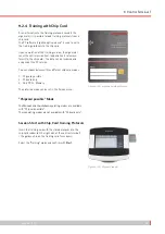
Page 65: ...the PC later on You can choose between three different chip card modes 1 Chipcard possible 2 Chipcard only 3 Only CPC Memory The preferred mode can be set in the Service menu Figure 9 49 ergoline trai...

Page 66: ...and confirm with Start The chip card training session proceeds in the same way as the training protocols stored in the ergometer Note It is NOT possible to edit the training protocols stored on the ca...

Page 67: ...card the user is prompted to remove it Remove the chip card from the control terminal After removal of the card the main menu of the ergometer is displayed again Please remove card Figure 9 55 Removin...

Page 68: ...ults and modifies the training protocol if necessary 5 While the training results on the chip card are analyzed by the physician therapist the patient can continue with the training sessions The train...

Page 69: ...oad Change on page 69 A blood pressure measurement is initiated with the RR key W 200 150 100 50 0 0 5 10 15 20 25 1 min 200 150 100 50 0 0 1 min 0 00 00 mm ss 0 1 min 0 W mmHg Waiting for start Start...

Page 70: ...ned on PC Mode Ergometry Training Test Manual and confirm the selection with the key Menu PC Mode Ergometry Training Test Manual Default Mode Figure 9 59 Setup default mode ECG Type The selected ECG T...

Page 71: ...l commands Digital default The communication with the ergometer is entirely controlled with digital commands Analog IN OUT The entire communication load control and BP mea surements is controlled with...

Page 72: ...30 06 2021 Figure 9 63 Setup date and time screen 1 Date 12 12 2019 Time 9 00 15 Date Time Second s 0 s 59 s 0 s 59 s 1 1 2 2 3 3 4 4 5 5 6 6 0 0 7 7 8 8 9 9 Second s Figure 9 64 Setup date and time...

Page 73: ...1 min Min 1 min Figure 9 66 Setup RPM screen 2 Software Version This menu shows the software version and the date of the next technical inspection of the measuring system MTK Software Version EF 1 X M...

Page 74: ...70 Setup protocols screen 3 At Type you can choose Step Ramp or Inactive You scroll through the Type options with the key When choosing the Step type load increase in steps define the basic load from...

Page 75: ...Recovery 3 min Load 3 W Figure 9 74 Editing the training test protocol The individual parameters light gray fields can now be edited by touching the display or by repeatedly tapping If you need to inp...

Page 76: ...f the test subject wears a chest strap to measure the heart rate during the training the corresponding chest strap number must be entered here You will find the number on the back of the housing It is...

Page 77: ...pping the light gray text field Regulation Load control normal Duration load 3 min Duration load 3 min Figure 9 79 Setup regulation method screen 1 When you touch the light gray fields to the right of...

Page 78: ...ttings can be configured see figure 9 83 To edit a setting touch the corresponding menu item on the display Confirm inputs with the key and exit menus with the key 1 Display HR monitoring Copy HR belt...

Page 79: ...his insert a chip card and then press the Export to CPC key All ID numbers will be copied from the memory of the ergometer to the chip card First however check that there are no training data on the c...

Page 80: ...nitial load manual training screen 1 After touching the light gray field to the right of Initial Load man see figure 9 88 the value can be entered via the numeric keypad With the key the input is conf...

Page 81: ...12 Blood pressure cuff metal D ring pediatric Measurement optional erg701 216 SpO2 SoftTip large length 1 20 m Measurement included erg701 225 SpO2 SoftTip medium length 1 20 m Measurement included er...

Page 82: ...5 10 2 Compatible Devices A large number of ECG and ergospirometry devices as well as PC software programs are compatible with ergoline ergometers via the ergoline interface protocol P10Vnnn Please co...

Page 83: ...Disinfection and General Hygiene Measures The document Cleaning and Disinfection ergoline Medical Devices Part No 201000641000 in its most recent version is also part of this manual This document is...

Page 84: ...sual inspection the device should be switched on and the proper functioning of the control panel should be verified This will ensure the proper functioning of the device the proper functioning of the...

Page 85: ...al must not be disposed of as unsorted municipal waste it must be collected separately Please contact your authorized manufacturer ergoline GmbH for information concerning the disposal of your equipme...

Page 86: ...8 Speed range 30 130 RPM Load accuracy to DIN VDE 0750 0238 Load increments user configurable Internal protocols Control Terminal P 5 fixed and 5 user configurable exercise test protocols manual load...

Page 87: ...xels and 7 segment RPM display Interfaces PORT 1 DSUB 9 pole remote control from PC or ECG recorder remote start of an ECG recorder option USB remote control from PC driver required optional Bluetooth...

Page 88: ...during inflation the inflation pressure auto matically adapts to patient s BP Inflation rate between approx 6 seconds to 140 mmHg and approx 18 seconds to 300 mmHg Max cuff pressure 300 mmHg Cuff def...

Page 89: ...min Load Stage W Recovery Load W Recovery Time min 1 WHO 25 2 25 25 99 2 BAL 50 3 50 25 99 3 Hollmann 30 3 40 25 99 4 STD France 30 3 30 25 99 5 Standard 20 1 25 25 99 6 15 user configurable 25 2 25 2...

Page 90: ...10 0 1 min rpm Load Watt 25 100 200 300 400 500 600 700 800 900 1000 Figure 13 1 black speed independent range to DIN VDE 0750 0238 black gray speed independent range of the ergoselect ergometer 13 8...

Page 91: ...d be tested to verify normal operation in the configuration in which it is being used Guidance and Manufacturer s Declaration Electromagnetic Emissions The ergoselect ergometer is intended for use in...

Page 92: ...ge to EN 61000 4 5 1 kV differential mode 2 kV common mode 1 kV N A Mains power quality should be that of a typical commercial or hospital environment Voltage dips short inter ruptions and voltage var...

Page 93: ...ce in meters m Field strengths from fixed RF trans mitters as determined by an electro magnetic site surveya should be less than the compliance level in each frequency rangeb Interference may occur in...

Page 94: ...utput power of the communications equipment Rated maximum output power of transmitter W Separation Distance according to Frequency of Transmitter m 150 kHz to 80 MHz d 1 2 P 80 MHz to 800 MHz d 1 2 P...

Page 95: ......
Page 96: ...ergoline GmbH Lindenstra e 5 72475 Bitz Germany Tel 49 0 7431 98 94 0 Fax 49 0 7431 98 94 128 e mail info ergoline com http www ergoline com...

Reviews: