


EPSON Stylus Pro 9500
Revision A
Adjustment
Adjustment Steps
215
P THICK SENSOR ASSEMBLY ADJUSTMENT
When removing/replacing the P THICK sensor, verify the sensor operation
using the Self-Diagnostic mode as described below.
1.
Press the following buttons and turn on the printer to enter the Self-
Diagnostics mode.
[Paper Feed
↓]
+
[Cut/Eject]
+
[Cleaning]
2.
Press the SelecType or Item button until "Check: Test" appears in the LCD,
then press the Enter button to select the Test menu.
3.
Press the SelecType or Item button until "Test: Sensor" appears in the
LCD, then press the Enter button to select the Test Item menu.
4.
Press the SelecType or Item button until "Sen: Paper xxxx" appears.
5.
Raise the Release lever to the "Release" position, and verify that "Sen:
Paper Thick" appears in the LCD.
6.
Insert a schema gauge (0.6mm/0.7mm) between the PF Grid Rollers and
Driven Rollers nearest the HP. Lower the Release lever to the "Lock"
position. The LCD message will vary according to the schema gauge as
shown in the table below.
7.
If the correct message does not appear or any other message appears,
verify the P THICK sensor is installed correctly and check the operation
again.
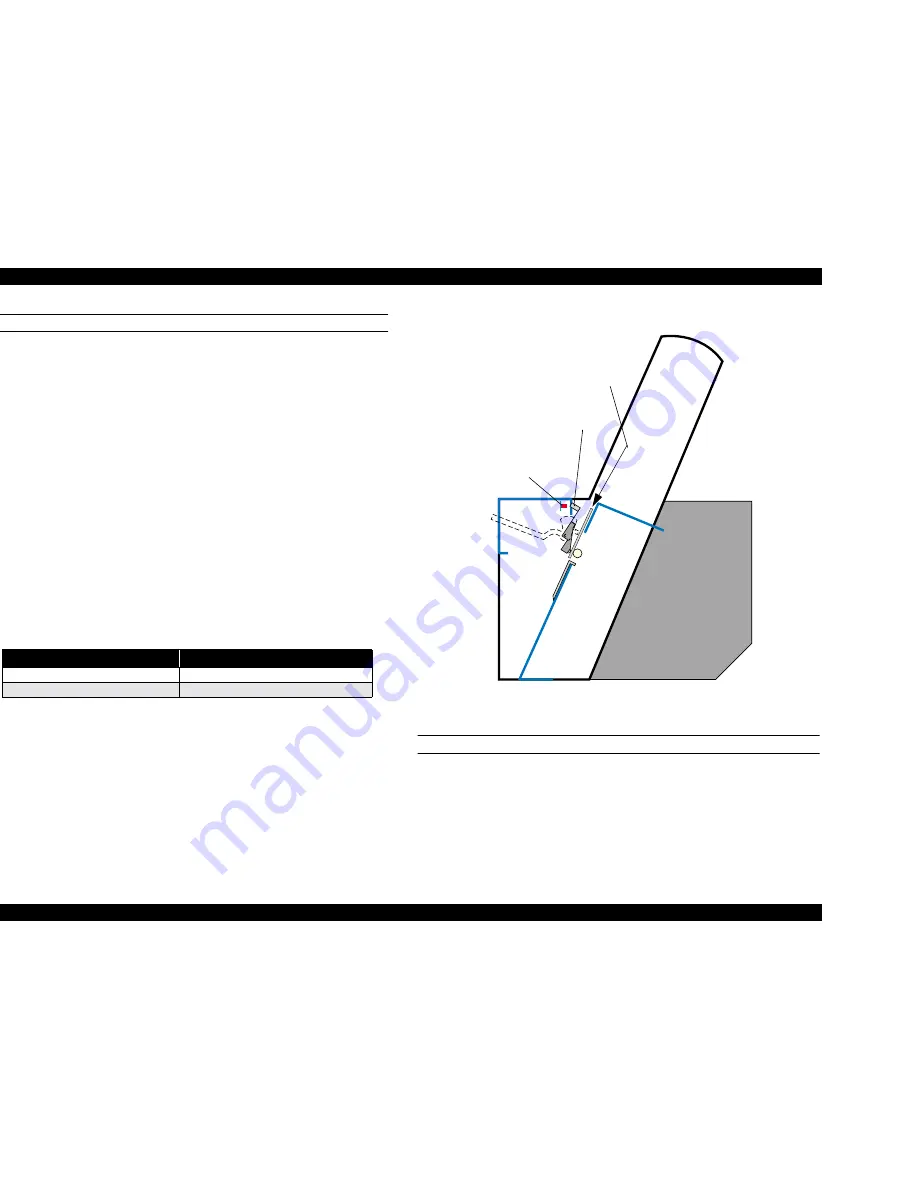
Figure 5-28. P Thick Sensor Adjustment
COVER, R/L SENSOR ASSEMBLY ADJUSTMENT
When the cover R/L sensor assembly is removed and installed, or the front
cover assembly is removed and installed, the cover R/L sensor assembly’s
installation position should be adjusted before the H-Top cover and R/L side
Table 5-20. P THICK Sensor Operation Check
Schema Gauge
LCD Message
0.7mm (thick paper)
Sen: Paper Wide
0.6mm (standard paper)
Sen: Paper Std
P Thick
Sensor
Flag
Insert the schema
gauge between
the Grid roller and
the Secondary
roller.
Summary of Contents for Stylus Pro 9500 Engine
Page 6: ...C H A P T E R PRODUCTDESCRIPTION ...
Page 43: ...C H A P T E R OPERATINGPRINCIPLES ...
Page 69: ...C H A P T E R TROUBLESHOOTING ...
Page 82: ...C H A P T E R DISASSEMBLY ASSEMBLY ...
Page 155: ...C H A P T E R ADJUSTMENT ...
Page 219: ...C H A P T E R MAINTENANCE SETUP ...
Page 232: ...C H A P T E R APPENDIX ...
Page 250: ...PSON Stylus Pro 9500 Revision A ppendix Exploded view Diagram 250 Figure 7 3 R Frame Assembly ...
Page 251: ...PSON Stylus Pro 9500 Revision A ppendix Exploded view Diagram 251 Figure 7 4 PF Rail Assembly ...
Page 252: ...PSON Stylus Pro 9500 Revision A ppendix Exploded view Diagram 252 Figure 7 5 CR Rail Assembly ...
Page 253: ...PSON Stylus Pro 9500 Revision A ppendix Exploded view Diagram 253 Figure 7 6 CR Assy ...
Page 254: ...PSON Stylus Pro 9500 Revision A ppendix Exploded view Diagram 254 Figure 7 7 Maintenance Assy ...
Page 255: ...PSON Stylus Pro 9500 Revision A ppendix Exploded view Diagram 255 Figure 7 8 I H Assy Left ...
Page 256: ...PSON Stylus Pro 9500 Revision A ppendix Exploded view Diagram 256 Figure 7 9 I H Assy Right ...
Page 257: ...PSON Stylus Pro 9500 Revision A ppendix Exploded view Diagram 257 Figure 7 10 I H Assy 1 ...
Page 258: ...PSON Stylus Pro 9500 Revision A ppendix Exploded view Diagram 258 Figure 7 11 I H Assy 2 ...
Page 259: ...PSON Stylus Pro 9500 Revision A ppendix Exploded view Diagram 259 Figure 7 12 Tube Assembly ...
Page 260: ...PSON Stylus Pro 9500 Revision A ppendix Exploded view Diagram 260 Figure 7 13 Board Assembly ...
Page 261: ...PSON Stylus Pro 9500 Revision A ppendix Exploded view Diagram 261 Figure 7 14 Cover Assembly ...
Page 265: ......
Page 266: ......


