


EPSON Stylus Pro 9500
Revision A
Adjustment
Adjustment Steps
162
5.2.1.1 Operating Procedure
Backup to a PC card and transfer of parameter data from a PC card to NVRAM
on the main board is accomplished by the following procedure.
BACKUP OF PARAMETERS TO A PC CARD
o
Backing up (uploading) data to the PC card
1.
Remove the access cover the top of the Upper Paper Guide, if necessary.
Also, make sure the Control Panel unit is attached.
2.
Insert the PC card into the PC card slot connector on the Main Board, and
then turn on the printer.
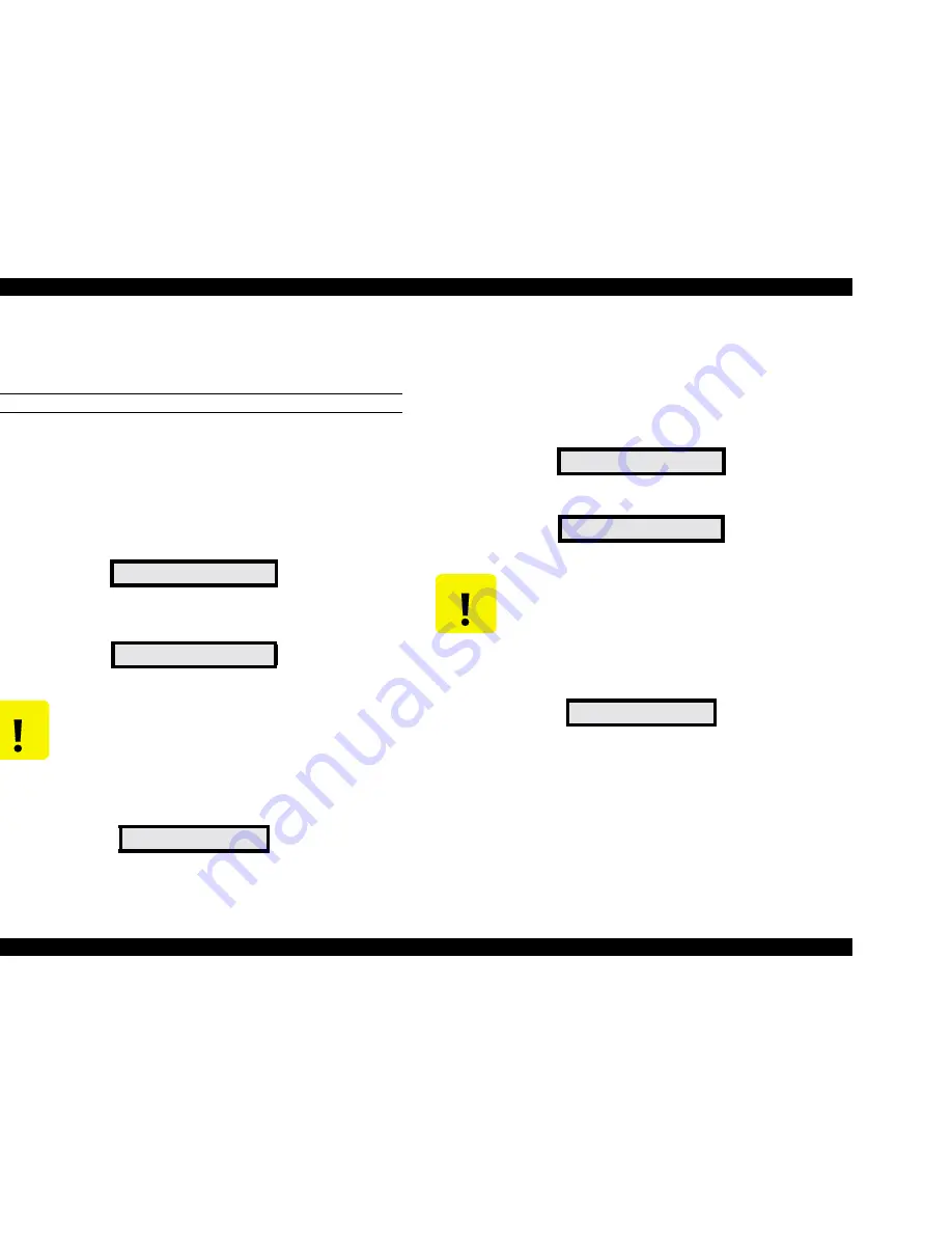
3.
Make sure the following message appears on the LCD, and wait for the
procedure to begin.
4.
The backup procedure starts about 15 seconds after the message
appears.
5.
When the backup procedure is finished, the following message appears.
6.
After making sure the printer is finished, turn off the printer and remove the
PC card.
o
Downloading the data from the PC card to the printer
1.
Make sure the access cover is removed from the top of the Upper Paper
Guide, add make sure the Control Panel is attached.
2.
Insert the PC card containing the backup data into the PC card slot
connector on the Main Board, and turn on the printer.
3.
Make sure the following message appears on the LCD.
4.
Press any button on the Control Panel to start the download procedure.
5.
When the download procedure is finished, the following message appears.
6.
After making sure the printer is finished, turn off the printer and remove the
PC card.
Wait:F->M Push:M->F
Flash -> Mcard
C A U T I O N
Do not touch the Control Panel buttons during this
procedure. Doing so causes the PC card to download
its data to the Main Board’s Flash memory instead of
backing up the data in Flash memory. This overwrites
the Flash memory so be careful.
End [Success]
Wait:F->M Push:M->F
Mcard -> Flash
C A U T I O N
If you wait 15 seconds before you press one of the
Control Panel buttons, the printer will start the backup
procedure instead of the download procedure. This
overwrites data stored in the PC card with data stored
in the Main Board Flash memory.
End [Success]
Summary of Contents for Stylus Pro 9500 Engine
Page 6: ...C H A P T E R PRODUCTDESCRIPTION ...
Page 43: ...C H A P T E R OPERATINGPRINCIPLES ...
Page 69: ...C H A P T E R TROUBLESHOOTING ...
Page 82: ...C H A P T E R DISASSEMBLY ASSEMBLY ...
Page 155: ...C H A P T E R ADJUSTMENT ...
Page 219: ...C H A P T E R MAINTENANCE SETUP ...
Page 232: ...C H A P T E R APPENDIX ...
Page 250: ...PSON Stylus Pro 9500 Revision A ppendix Exploded view Diagram 250 Figure 7 3 R Frame Assembly ...
Page 251: ...PSON Stylus Pro 9500 Revision A ppendix Exploded view Diagram 251 Figure 7 4 PF Rail Assembly ...
Page 252: ...PSON Stylus Pro 9500 Revision A ppendix Exploded view Diagram 252 Figure 7 5 CR Rail Assembly ...
Page 253: ...PSON Stylus Pro 9500 Revision A ppendix Exploded view Diagram 253 Figure 7 6 CR Assy ...
Page 254: ...PSON Stylus Pro 9500 Revision A ppendix Exploded view Diagram 254 Figure 7 7 Maintenance Assy ...
Page 255: ...PSON Stylus Pro 9500 Revision A ppendix Exploded view Diagram 255 Figure 7 8 I H Assy Left ...
Page 256: ...PSON Stylus Pro 9500 Revision A ppendix Exploded view Diagram 256 Figure 7 9 I H Assy Right ...
Page 257: ...PSON Stylus Pro 9500 Revision A ppendix Exploded view Diagram 257 Figure 7 10 I H Assy 1 ...
Page 258: ...PSON Stylus Pro 9500 Revision A ppendix Exploded view Diagram 258 Figure 7 11 I H Assy 2 ...
Page 259: ...PSON Stylus Pro 9500 Revision A ppendix Exploded view Diagram 259 Figure 7 12 Tube Assembly ...
Page 260: ...PSON Stylus Pro 9500 Revision A ppendix Exploded view Diagram 260 Figure 7 13 Board Assembly ...
Page 261: ...PSON Stylus Pro 9500 Revision A ppendix Exploded view Diagram 261 Figure 7 14 Cover Assembly ...
Page 265: ......
Page 266: ......


