


EPSON Stylus Pro 9500
Revision A
Disassembly & Assembly
Disassembly Flow
146
HEAD GAP ADJUSTMENT (ALIGNMENT BETWEEN HEADS)
This adjustment is performed for the following purpose.
n
The GAP adjustment printing mode has been changed together
with the update to the new firmware (pigment ink), so a new
adjustment is necessary.
The following 2 items related to the GAP adjustment in the pigment ink
firmware are adjusted.
NOTE:
NOTE: The numbers in the above table are printed at the
beginning of the printing pattern when the adjustment pattern is
printed and show the adjustment pattern No.
1.
After inputting the Bi-D adjustment, confirm that “Bi-D End” is displayed in
the LCD. The program will move to the Head Gap adjustment mode, so
press the [Enter] button.
2.
Confirm that “Adj: Head LR Adj” is displayed in the LCD. Press the [Enter]
button to print the adjustment pattern.
C A U T I O N
n
Up to Bi-D adjustment patterns No. 1 ~ 3, by deciding
the value input from the panel, the adjustment
results are printed out, so it is possible to check the
adjustment results visually, but for Bi-D adjustment
pattern No. 4, even if you decide a value to input from
the panel, a printing pattern that reflects the
adjustment results is not printed, so the adjustment
results cannot be checked visually. Therefore, if you
are confirming the adjustment results for adjustment
values by printing pattern, the following DOS
program becomes necessary.
* Program Transfer Utility: Pout3.Exe
* Program Name:Bid333.prn
The program transfer method is as follows.
1.
Confirm that the printer is in the Pause state.
2.
Move to the DOS prompt.
3.
Input “POUT__BID333.PRN.”
4.
Press the Enter key.
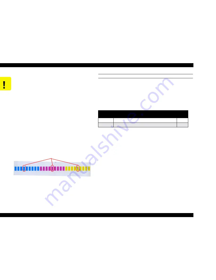
Through the above operation, a total of 9 blocks of
printing patterns are printed out in each color. The results
from the adjustment values input in the Adjustment mode
are positioned in the center pattern of the 9-block pattern
of each color.
Adjustment Results
Table 4-10. Head Gap Adjustment Items
Item
Description
Numbe
r
Gap/200/M
Head GAP adjustment / 240 cps / Normal Dot
#5
Gap/300/N
Head GAP adjustment / 333 cps / Normal Dot
#6
Summary of Contents for Stylus Pro 9500 Engine
Page 6: ...C H A P T E R PRODUCTDESCRIPTION ...
Page 43: ...C H A P T E R OPERATINGPRINCIPLES ...
Page 69: ...C H A P T E R TROUBLESHOOTING ...
Page 82: ...C H A P T E R DISASSEMBLY ASSEMBLY ...
Page 155: ...C H A P T E R ADJUSTMENT ...
Page 219: ...C H A P T E R MAINTENANCE SETUP ...
Page 232: ...C H A P T E R APPENDIX ...
Page 250: ...PSON Stylus Pro 9500 Revision A ppendix Exploded view Diagram 250 Figure 7 3 R Frame Assembly ...
Page 251: ...PSON Stylus Pro 9500 Revision A ppendix Exploded view Diagram 251 Figure 7 4 PF Rail Assembly ...
Page 252: ...PSON Stylus Pro 9500 Revision A ppendix Exploded view Diagram 252 Figure 7 5 CR Rail Assembly ...
Page 253: ...PSON Stylus Pro 9500 Revision A ppendix Exploded view Diagram 253 Figure 7 6 CR Assy ...
Page 254: ...PSON Stylus Pro 9500 Revision A ppendix Exploded view Diagram 254 Figure 7 7 Maintenance Assy ...
Page 255: ...PSON Stylus Pro 9500 Revision A ppendix Exploded view Diagram 255 Figure 7 8 I H Assy Left ...
Page 256: ...PSON Stylus Pro 9500 Revision A ppendix Exploded view Diagram 256 Figure 7 9 I H Assy Right ...
Page 257: ...PSON Stylus Pro 9500 Revision A ppendix Exploded view Diagram 257 Figure 7 10 I H Assy 1 ...
Page 258: ...PSON Stylus Pro 9500 Revision A ppendix Exploded view Diagram 258 Figure 7 11 I H Assy 2 ...
Page 259: ...PSON Stylus Pro 9500 Revision A ppendix Exploded view Diagram 259 Figure 7 12 Tube Assembly ...
Page 260: ...PSON Stylus Pro 9500 Revision A ppendix Exploded view Diagram 260 Figure 7 13 Board Assembly ...
Page 261: ...PSON Stylus Pro 9500 Revision A ppendix Exploded view Diagram 261 Figure 7 14 Cover Assembly ...
Page 265: ......
Page 266: ......


