background image

SC-T7000 series/SC-T5000 series/SC-T3000 series

Revision B

ADJUSTMENT

Media Feed Related Checks and Adjustments

265

Confidential

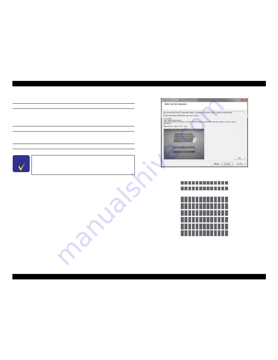
4.13.3  Media Feed Auto Adjustment

PAPER USED

†

Type: 

Premium Glossy Photo Paper (250)

†

Size: 

16 inches or longer

EXECUTION MODE

Normal mode

PROCEDURE

1. Turn the printer ON.

2. Load the paper into the printer.

3. Start the Service Program and select 

Media Feed Auto Adjustment

.

4. Click 

[Run]

The adjustment pattern will be printed.

5. After the pattern is printed, the printer will automatically scan the pattern and carry 

out the adjustment (no manual adjustment is needed).

6. Click 

[Finish]

.

7. Turn the printer OFF to finish the adjustment.

Figure 4-62.  [Media Feed Auto Adjustment] Screen

Figure 4-63.  Adjustment Pattern

C H E C K

P O I N T

Required time: about 4 minutes

Summary of Contents for SC-T3000

Page 1: ...SC T7000series SC T5000series SC T3000series Large Format Color Inkjet Printer SERVICE MANUAL SEIJ12008 Confidential ...

Page 2: ... of this manual However should any errors be detected SEIKO EPSON would greatly appreciate being informed of them The above not withstanding SEIKO EPSON CORPORATION can assume no responsibility for any errors in this manual or the consequences thereof EPSON is a registered trademark of SEIKO EPSON CORPORATION General Notice Other product names used herein are for identification purpose only and ma...

Page 3: ...EMBLING OR ASSEMBLING A PRODUCT MAKE SURE TO WEAR GLOVES TO AVOID INJURY FROM METAL PARTS WITH SHARP EDGES WARNING 1 REPAIRS ON EPSON PRODUCT SHOULD BE PERFORMED ONLY BY AN EPSON CERTIFIED REPAIR TECHNICIAN 2 MAKE CERTAIN THAT THE SOURCE VOLTAGES IS THE SAME AS THE RATED VOLTAGE LISTED ON THE SERIAL NUMBER RATING PLATE IF THE EPSON PRODUCT HAS A PRIMARY AC RATING DIFFERENT FROM AVAILABLE POWER SOU...

Page 4: ...RIPTIONS Provides a general overview and specifications of the product CHAPTER 2 TROUBLESHOOTING Describes the step by step procedures for the troubleshooting CHAPTER 3 DISASSEMBLY ASSEMBLY Describes the step by step procedures for disassembling and assembling the product CHAPTER 4 ADJUSTMENT Provides Epson approved methods for adjustment CHAPTER 5 MAINTENANCE Provides preventive maintenance proce...

Page 5: ...f equipment May indicate an operating or maintenance procedure practice or condition that is necessary to accomplish a task efficiently It may also provide additional information that is related to a specific subject or comment on the results achieved through a previous action Indicates an operating or maintenance procedure practice or condition that if not strictly observed could result in injury...

Page 6: ...cription A October 1 2012 First release B March 6 2013 Chapter 2 2 3Remedies for Service Call Error p 43 partially deleted Chapter4 4 1 2Adjustment Items and the Order by Repaired Part p 199 partially revised 4 14 1Main Board initial setting p 270 was added ...

Page 7: ...of the trouble 40 2 1 1 4 Check for the counter values history 40 2 1 1 5 Test print check 40 2 1 2 Troubleshooting Procedure 41 2 1 3 Procedure after troubleshooting 41 2 1 3 1 If the trouble has been successfully solved 41 2 1 3 2 If necessary to escalate the trouble case 41 2 2 Remedies for Maintenance Requests 42 2 3 Remedies for Service Call Error 43 2 4 Remedies for Print Quality Troubles 58...

Page 8: ...3 4 4 14 IC HOLDER 148 3 4 4 15 INK TUBE 152 3 4 4 16 CR UNIT 156 3 4 4 17 IM SENSOR 159 3 4 4 18 PW SENSOR 161 3 4 5 Paper Feed Mechanism 163 3 4 5 1 PF MOTOR 163 3 4 5 2 PF SCALE 165 3 4 5 3 PF ENCODER 166 3 4 5 4 PF TIMING BELT 168 3 4 5 5 PRESSURE ROLLER 170 3 4 5 6 PRESSURE ROLLER MOTOR 171 3 4 5 7 PRESSURE ROLLER SENSOR 173 3 4 5 8 ATC MOTOR 175 3 4 5 9 PE SENSOR ROLL PAPER 177 3 4 5 10 PE S...

Page 9: ... 3 Correcting Head Slant PF direction 258 4 12 Ink Supply Related Checks and Adjustments 259 4 12 1 Ink eject 259 4 12 2 Cleaning Tube Inner Cleaning 260 4 12 3 Initial Ink Charge 261 4 13 Media Feed Related Checks and Adjustments 262 4 13 1 PF Belt Tension Check 262 4 13 2 PC Scale Check 264 4 13 3 Media Feed Auto Adjustment 265 4 13 4 Cut Position Check Adjustment 266 4 13 5 Paper Thickness Sens...

Page 10: ...Confidential C H A P T E R 1 PRODUCTDESCRIPTION ...

Page 11: ...sed on ergonomics Supports continuous printing of drawings or posters in a standard size such as A0 A1 or US ANSI D E Translucent printer cover allows you to check which roll paper is loaded easily Space saving design Front access design allows you to set the printer near a wall because you can exchange the media ink cartridges maintenance box and cutter from the front New driver and applications ...

Page 12: ...ed 20 C to 40 C within 1 month under 40 C Humidity Main body operation environment 20 to 80 Non condensing When storing packed 5 to 85 Non condensing When storing unpacked 5 to 85 Non condensing Row A Row B Row C Row D Row E Row F Row G Row H Row I Row J C M Y PK MK MK PK Y M C Item Specification SC T7000 series SC T5000 series SC T3000 series Rated voltage 100 to 240 VAC Input voltage range 90 to...

Page 13: ...ed on the package at normal temperature Guaranteed life after installation 1 year after mounted in the printer Storage Uninstalled packed 20 to 40 C within 4 days under 20 C and within 1 month under 40 C Installed 20 to 40 C within 4 days under 20 C and within 1 month under 40 C Transporting packed 20 to 60 C within 4 days under 20 C within 1 month under 40 C and within 72 hours under 60 C Capacit...

Page 14: ...TION Printing Specifications 14 Confidential 1 3 Printing Specifications 1 3 1 Paper Feed Specifications Item Specification Paper feed method Friction feed Return pitch 2 2049 μm 1 11 520 inch Paper feeder Roll paper manual feed Cut sheet manual feed Feed speed 300ms 1 6 inch ...

Page 15: ...int 6 Take up 3 Enlarged 5 Head Alignment ICC Profile mm inch Forward Backward Premium Glossy Photo Paper 250 406 16 0 27 3 EPSON SC T3000_5000_7000_Series Premium Glossy Photo Paper 250 icc 610 24 914 1 36 1 1118 2 44 2 Premium Semigloss Photo Paper 250 406 16 0 27 3 EPSON SC T3000_5000_7000_Series Premium Semigloss Photo Paper 250 icc 610 24 914 1 36 1 1118 2 44 2 Premium Luster Photo Paper 260 ...

Page 16: ...nced Synthetic Paper icc 1118 2 44 2 Enhanced Adhesive Synthetic Paper 610 24 0 18 2 U EPSON SC T3000_5000_7000_Series Enhanced Adhesive Synthetic Paper icc 1118 2 44 2 Doubleweight Matte Paper 610 24 0 21 2 4 EPSON SC T3000_5000_7000_Series Doubleweight Matte Paper icc 914 1 36 1 1118 2 44 2 Enhanced Matte Paper 432 17 0 25 3 U EPSON SC T3000_5000_7000_Series Enhanced and Archival Matte Paper icc...

Page 17: ...um Glossy Photo Paper icc A2 US C U Premium Semigloss Photo Paper Super A3 B 0 27 U EPSON SC T3000_5000_7000_Series Premium Semigloss Photo Paper icc A2 US C U Premium Luster Photo Paper Super B 0 27 U EPSON SC T3000_5000_7000_Series Premium Luster Photo Paper icc A2 US C U Archival Matte Paper Enhanced Matte Paper Super A3 B 0 26 U EPSON SC T3000_5000_7000_Series Enhanced and Archival Matte Paper...

Page 18: ...aper types manufactured by other companies can be loaded in the printer as long as they meet the following specifications Epson cannot guarantee the paper feeding and print quality Item Specification Media types Plain paper and recycled paper Paper core size 2 inch and 3 inch Roll paper outer diameter 150 mm or less Width SC T7000 Series 254 mm 10 inches to 1 118 mm 44 inches SC T5000 Series 254 m...

Page 19: ...SC T7000 Series 210 mm A4 to 1 118 mm 44 inches SC T5000 Series 210 mm A4 to 914 mm 36 inches SC T3000 Series 210 mm A4 to 610 mm 24 inches Length 279 4 to 1 580 mm Paper thickness 0 08 to 0 8 mm Available width for borderless printing 254 mm 10 inch 300 mm 11 8 inch Super A3 B 329 mm 406 mm 16 inch 17 inch B2 515 mm A1 594 mm 610 mm 24 inch 728 mm A0 841 mm 914 mm 36 inch 1030 mm 1118 mm 44 inch ...

Page 20: ...m Semigloss Photo Paper 250 Premium Luster Photo Paper 260 Premium Semimatte Photo Paper 260 When the following media are used in the CAD Line Drawing mode the value for A and C is 3 mm Singleweight Matte Paper CUT SHEET Table 1 1 Roll Paper Margin Roll Paper Margin Parameter Margin Values Normal A C 15mm B D 3mm Top15mm Bottom15mm A C 15mm B D 3mm Top35mm Bottom15mm A 35mm C 15mm B D 3mm 3 45mm 3...

Page 21: ... multiple sheets the printer cuts 1 mm inside on the top edge of the first page and the bottom edge of the subsequent pages to avoid showing margins A B A B Double Cut The top area may become slightly uneven depending on the image since the print operation stops while cutting the top edge of the roll paper The printed paper is approximately 2 mm shorter than the specified size since the printer cu...

Page 22: ...1 When the paper basket is retracted 2 Excluding ink cartridges 1 4 2 Installation Room Requirement Figure 1 1 SC T7000 Series SC T5000 Series Figure 1 2 SC T3000 Series Model Width Depth 1 Height Weight 2 SC T7000 Series 1 608 mm 813 mm 1 128 mm Approx 82 kg SC T5000 Series 1 405 mm 813 mm 1 128 mm Approx 75 kg SC T3000 Series w o dedicated stand 1 050 mm 691 mm 613 mm Approx 51 kg SC T3000 Serie...

Page 23: ...er cover 2 Poster board support 3 Maintenance box covers 4 Paper basket 5 Casters 6 Stack guides 7 Stack guide switch lever 8 Cartridge cover 9 Ink cartridges 10 AC inlet 11 Option port 12 LAN port 13 Data light 14 Status light 15 USB port 16 Control panel 17 Alert lamp 18 Roll rest 19 Adapter guides 20 Roll lock lever 21 Adapter holder 22 Paper slot 23 Print head 24 Roll paper cover 25 Paper ejec...

Page 24: ... T5000 series SC T3000 series Revision B PRODUCT DESCRIPTION Hardware Specifications 24 Confidential ROLL PAPER ADAPTER Figure 1 4 Roll paper adapter Table 1 5 Roll paper adapter No Name 1 Adapter lock lever 2 Size lever ...

Page 25: ...ttons Use these buttons to select tabs 8 Up Down buttons When menus are displayed these buttons can be used to highlight items or options 9 OK button Displays the menu for the tab currently selected in the display When menus are displayed and an item is highlighted pressing this button displays the sub menu for the highlighted item If pressed while a parameter is selected from the Menu the paramet...

Page 26: ...n be used to access the Paper menu Ink Tab Displays ink status The ink cartridge status is indicated as follows No error Ink is low Ink cartridge is expended An error occurred Non genuine cartridge is installed Maintenance Tab Shows the status of the Maintenance Box and is used to display the Maintenance menu Maintenance Box status is shown as follows No error The Maintenance Box is nearing the en...

Page 27: ...sis of the amount of ink remaining when documents are printed using LFP Print Plug In for Office or EPSON CopyFactory5 Hold Queue 1 View Hold Queue XXXXXXXXXXX name of held print job Paused Job Name User Paper Type Source Size Reason For Hold This option is available only if On is selected for Store Held Job in the Setup menu Displays the print settings for held jobs and the reason the job is held...

Page 28: ...per Others Custom Paper Select the name of the custom paper loaded in the printer Custom Paper Setting XXXXXXXXXXX name of custom paper type Select Reference Paper Photo Paper You can select the media type that is the closest to the paper you are using Matte Paper Plain Paper Others No Paper Selected Select this option if you do not wish to specify the paper type Platen Gap Narrow Select the plate...

Page 29: ...e pattern will be displayed in the control panel Press the S T buttons to enter the measured value and press the OK button When Value is selected Choose an adjustment between 0 70 and 0 70 Selecting too small a value causes dark bands adjust the amount upward Similarly choosing too large a value causes white bands adjust the amount downward Value Paper Suction 4 to 0 It is important to choose the ...

Page 30: ...ual Uni D Manual Bi D Cutter Maintenance Adjust Cut Position 3 to 3 mm You can fine tune the cut position when printing to roll paper with no margins in all directions The cut position can be adjusted in increments of 0 2 mm Replace Cutter Moves the cutter to the replacement position so it can be replaced Press the OK button to move the cutter to the replacement position The paper must be removed ...

Page 31: ...ing Availability The printer will estimate printing availability based on the length of the roll Off Remaining Alert 1 to 15 m 4 to 50 ft Displayed when On is selected for Roll Paper Remaining Set within a range from 1 to 15 m 4 to 50 ft to display a warning when the amount of remaining roll paper drops below that limit You can set in 0 5 m 1 ft increments Advanced Settings Roll Paper Tension Low ...

Page 32: ...tances as skewed paper may cause the printer to jam Off Store Held Job On This item is available when an optional hard disk unit is installed If On is selected print jobs that require a paper type source or output paper size width that differs from those currently selected with the printer will be saved as held jobs select Off to disable this feature If Off is selected an error will be displayed a...

Page 33: ...turns off automatically when there are no errors no print jobs being received and no control panel or other operations are performed for eight hours The delay before the printer turns off can be selected from values between 1 and 24 hours in increments of 1 hour Choose Off to prevent the printer turning off automatically 1 to 24 hours Restore Settings Yes Select Yes to restore all Power Settings t...

Page 34: ...ng areas To select all nozzles place a check in the box on the left Manage HDD Format Hard Disk Yes Select Yes to format the optional hard disk unit currently attached to the printer Formatting the hard disk unit deletes all stored print jobs Hard disk units that have been used with other printers must be formatted before they can be used this printer No Date And Time MM DD YY HH MM Set the printe...

Page 35: ... still 36 inches To print without borders select Borderless The sizes available vary with the scanner Borderless Other Size Document Size A3 B4 A4 B5 A5 LTR 4x6 Select the size of the original document when copying at other sizes The sizes available vary with the scanner Output Size A0 US E B1 A1 USD B2 US C A2 A0 2Sheets Choose the output size when copying at other sizes A0 2Sheets is available o...

Page 36: ...d OK buttons together 2 Turn the printer off to quit the Serviceman Mode SERVICEMAN MODE MENU LIST Menu Explanation Class 1 2 3 Mecha Adjustment Paper Adjusts the detection accuracy of the PAPER THICKNESS SENSOR Rear AD Adjusts the AD value of the PE Sensor CR Un Cap Unlocks or re locks the carriage and uncaps re caps the Print Head LCD RGB Check Red Checks the operation of the LCD Green Blue Pane...

Page 37: ...PTION Control Panel Specifications 37 Confidential Life CR PG PG Used only in manufacturing processes Not used in service operations PG PGtyp PG PG H to F Speed 400 CPS 500 CPS 240 CPS F to H Speed 400 CPS 500 CPS 240 CPS Page Size Fan Life Count Menu Explanation Class 1 2 3 ...

Page 38: ...PF Feed Amount 1 Used only in manufacturing processes Not used in service operations Feed Speed 1 PS1 PS2 PS3 PS4 Feed Amount 2 Feed Speed 2 PS1 PS2 PS3 PS4 Wait Fan Life Count RLS Wait1 Wait2 Life Count APG PG PG PG PGtyp PG PG Wait Life Count Cutter Length Return Length Wait Life Count Display Count Menu Explanation Class 1 2 3 ...

Page 39: ...Confidential C H A P T E R 2 TROUBLESHOOTING ...

Page 40: ...ck if the trouble the user claims recurs with the returned printer If RIP was used check if the trouble recurs when the driver is used If 3rd party s media were used check if the trouble recurs when a genuine medium is used If 3rd party s ink was used perform the repair according to the policy of each local sales subsidiary If the F W was not the latest gain agreement with the user on the update o...

Page 41: ...epair follow your company local office s policy 2 1 3 2 If necessary to escalate the trouble case Make a report with the following data Backed up NVRAM data For bad print quality a print sample with the marked symptom and a printed test pattern For faulty parts the faulty parts themselves and a photos of the troubling section Information on the user the repair listed below This is a format of the ...

Page 42: ...it 8 the date time not set Table 2 1 List of the Maintenance Requests Bit assignment Binary NNNN Hexa decimal Parts corresponding to the request Status 12 11 10 9 8 7 6 5 4 3 2 1 0 0 0 0 0 0 0 0 0 0 0 0 0 1 00000000 INK TUBE End of the life 0 0 0 0 0 0 0 0 0 0 0 1 0 00000002 PUMP CAP UNIT End of the life 0 0 0 0 0 0 0 0 0 0 1 0 0 00000004 PUMP CAP UNIT Near the end of life 0 0 0 0 0 0 0 0 0 1 0 0 ...

Page 43: ...lding plate react to the sensor 2 Is there any paper jammed inside the printer 3 Does the CR SCALE have any scratches or dirt 4 Does the CR ENCODER work properly Check it using the Service Program 5 Does the CR Lock function normally 1 Replace the CR HP SENSOR See P 143 2 Re install the CR ENCODER If it is faulty replace it See P 138 3 Clean the CR SCALE using ethanol 4 Replace the CR SCALE See P ...

Page 44: ...ersing error The number of occurrences of reversing the CR MOTOR has reached a predetermined limit The polarity of CR ENCODER cable is opposite The polarity of CR MOTOR cable is opposite Slipping of the teeth of CR TIMING BELT CR ENCODER failure 1 Check the following connection and installation direction CR ENCODER to SUB BOARD CN102 CR MOTOR to MAIN BOARD CN19 2 Check if the tension of the CR TIM...

Page 45: ...he PF ENCODER work properly Check it using the Service Program 1 Replace the PF ENCODER See P 166 2 Replace the MAIN BOARD See P 111 122B PF Over speed error The PF MOTOR was driven at a speed faster than a predetermined one during deceleration PF irregular load PF ENCODER failure SUB B BOARD is damaged PF MOTOR driver failure Does the PF ENCODER work properly Check it using the Service Program 1 ...

Page 46: ...over from the error 2 Is the FFC connected to the connector properly without being tilted 1 Replace the HEAD FFC See P 127 2 Replace the PRINT HEAD See P 126 1412 PUMP Pump life error The number of PUMP CAP UNIT operation has reached the specified limit The rotation of the pump motor has reached the specified limit Replace the PUMP CAP UNIT See P 147 and reset its counter See P 231 1416 PUMP Undet...

Page 47: ...coder work properly Check it using the Service Program Replace the pump motor encoder PUMP CAP UNIT See P 147 141D PUMP Driving time out error Abnormally long driving duration of the pump motor was detected Irregular load Firmware becomes out of control Replace the MAIN BOARD See P 111 141E PUMP Velocity deviation error The pump motor was driven at a speed abnormally faster than a predetermined on...

Page 48: ...oreign materials around the APG motor driver 1 Remove the foreign material 2 If the error still occurs replace the MAIN BOARD See P 111 151A APG Overload error Connection failure of the APG motor Overcurrent to the APG motor was detected APG motor cable is damaged Irregular load APG encoder failure APG motor failure Is there any problems such as damaged cable in the connections below APG motor APG...

Page 49: ...e PRESSURE ROLLER MOTOR driver on the MAIN BOARD damaged 2 Is there any foreign materials around the PRESSURE ROLLER MOTOR driver 1 Remove the foreign material 2 If the error still occurs replace the MAIN BOARD See P 111 153A Driven roller Overload error Overcurrent to the PRESSURE ROLLER MOTOR was detected PRESSURE ROLLER SENSOR cable is damaged PRESSURE ROLLER MOTOR cable is damaged Irregular lo...

Page 50: ... MOTOR failure PRESSURE ROLLER MOTOR driver failure Does the PRESSURE ROLLER MOTOR encoder work properly Check it using the Service Program 1 Replace the PRESSURE ROLLER MOTOR encoder cable PRESSURE ROLLER MOTOR See P 171 2 Replace the MAIN BOARD See P 111 153F Driven roller Lock error The PRESSURE ROLLER MOTOR was driven at a speed abnormally slower than a predetermined one during operation Irreg...

Page 51: ...ny problems such as damaged cable in the connections below Cutter motor cutter motor encoder to SUB B BOARD CN4 2 Does the cutter motor encoder work properly Check it using the Service Program Replace the cutter motor cutter motor encoder CUTTER UNIT See P 181 154D Cutter Driving time out error Abnormally long driving duration of the cutter motor was detected Irregular load Firmware becomes out of...

Page 52: ...lar load ATC MOTOR encoder failure APG MOTOR driver failure Does the ATC MOTOR encoder work properly Check it using the Service Program 1 Replace the ATC MOTOR See P 175 2 Replace the MAIN BOARD See P 111 159C ATC Reversing error The number of occurrences of reversing the ATC Motor has reached a predetermined limit The polarity of ATC MOTOR cable is opposite ATC MOTOR failure 1 Is there any proble...

Page 53: ...y 2 After several seconds re attach the battery and turn the power back on 3 Reset the date and time settings of the RTC using the Service Program 1A37 Thermistor error The HEAD FFC is not connected correctly A temperature out of a predetermined range was detected by the Head thermistor Head thermistor failure Is the HEAD FFC connected properly without being connected at an angle and any abnormali...

Page 54: ...ed at an angle and any abnormalities such as peeled terminals 1 Replace the FFC between the MAIN BOARD and SUB BOARD See P 131 2 Replace the SUB BOARD See P 115 3 Replace the MAIN BOARD See P 111 1A70 Hardware MAIN to MAIN B BOARD communication error TBD TBD TBD 1A71 Hardware MAIN B BOARD system error Core0 TBD TBD TBD 1A72 Hardware MAIN B BOARD system error Core1 TBD TBD TBD 1F10 Maintenance Main...

Page 55: ...eplace the IC HOLDER See P 148 2 Replace the MAIN BOARD See P 111 1FB9 CSIC control CSIC error CSIC control error 1 Replace the IC HOLDER See P 148 2 Replace the MAIN BOARD See P 111 1FBE CSIC control CSIC error CSIC control error 1 Replace the IC HOLDER See P 148 2 Replace the MAIN BOARD See P 111 1FBF CSIC control CSIC error CSIC control error 1 Replace the IC HOLDER See P 148 2 Replace the MAIN...

Page 56: ...ut nothing could be written to it Replace the MAIN BOARD See P 111 2003 Memory FLASH BOOT SUM CHECK error Installing the firmware has failed The Flash ROM is out of order 1 Re install the firmware Page 229 2 Replace the MAIN BOARD See P 111 2008 Memory Wrong FLASH device error TBD TBD TBD 200A Memory F W load error Reading decompressing the firmware has failed 1 Re install the firmware Page 229 2 ...

Page 57: ...sure unit IC HOLDER See P 148 2 If the error still occurs replace the MAIN BOARD See P 111 1621 Pressure motor Pressurizing Suction switching error The pressurizing and suction processes did not complete within a predetermined time period 1 Is there any abnormal load applied to the pressure unit 2 Is there any disconnected connectors or damaged cables 1 Replace the pressure unit IC HOLDER See P 14...

Page 58: ...the Cap 2 Replace the Cap PUMP CAP UNIT See P 147 There is some foreign material on the PRINT HEAD Is there any foreign materials on the PRINT HEAD Clean the PRINT HEAD There is something wrong in the pump tube and the cleaning suctioning of ink cannot be performed properly Is the pump tube being bent or getting caught between surrounding parts or components Route the pump tube correctly The ink i...

Page 59: ...paper thickness setting correct 2 Has the PG adjustment been made properly 1 Correct the paper thickness setting 2 Perform the PG adjustment Page 245 Bandings in the paper feeding direction The PRINT HEAD has not been adjusted properly Carry out the following adjustments Head inclination adjustment CR direction Page 253 Head slant adjustment PF direction Page 256 The paper was not fed properly Car...

Page 60: ...side is smudged or smeared with ink There is a problem with the paper used 1 Is the paper wrinkled bent rippled or warped 2 Is the paper too thick and contacting with the head 3 Is the paper too thin and loosening when being fed 1 Replace the paper with a new proper one 2 Adjust the PG setting according to the paper thickness Improper PG adjustment Has the PG adjustment been made properly Perform ...

Page 61: ...249 Paper dust is attached or the traces of the rollers appear Traces of Pressure Roller are caused because the paper had been kept set in the printer for a long time Remove the paper if the printer is left for a long time The paper dust attached on the PF rollers transferred to the paper Is there any paper dust attached to the PF rollers Clean the rollers Print some blank pages to clean them Tabl...

Page 62: ...ing failure SUCTION FAN failure 1 Is the suction setting proper 2 Does the SUCTION FAN work normally Check it using the Service Program 1 Make the suction setting properly 2 Replace the SUCTION FAN PF rollers failure Are the PF rollers contaminated or damaged Clean the rollers or replace them Paper is skewing The Paper Skew Check function has been disabled Enable select ON the Paper Skew Check fun...

Page 63: ...irmly inserted Is the cable breaking Is the cable being bent or is there anything placed on the cable Correct the problem LAN connector failure Is the connector deformed or damaged Replace the MAIN C BOARD The MAC address is invalid Rewrite the address with a correct one Page 272 Connection failure of the MAIN C BOARD Is there any problems in the connection between the MAIN C BOARD and the MAIN BO...

Page 64: ...e program is wrong Did you get the program through the official channel Check it with the license agreement displayed at the start up screen Download the program file including security files through the official channel More than one printers are connected to the computer Is there any printer connected to the USB port on the computer other than the one for adjustment Disconnect the printer which ...

Page 65: ...atus of the NVRAM Viewer 0 Hide 1 Show Adjust the setting according to the policy of each local sales subsidiary The contents and the items displayed in the NVRAM Viewer do not match with each other The Service Program you are running is different one Are you running the Service Program for this product Use the proper Service Program for this product History of the error and the counter reset are ...

Page 66: ...Confidential C H A P T E R 3 DISASSEMBLY ASSEMBLY ...

Page 67: ...he headings WARNING and CAUTION C H E C K P O I N T The disassembly assembly procedures are provided based on SC T7000 series The procedures for SC T5000 series SC T3000 series are basically the same unless otherwise specified W A R N I N G When the PRINTR COVER is opened a safety interlock mechanism causes the CR MOTOR and the PF MOTOR to stop When the interlock function is disabled be sure to ta...

Page 68: ...harnesses and such make sure to check visually if any harness is caught in between or any wrong connection exists C A U T I O N Locate the printer on a stable and flat surface Use only recommended tools for disassembly assembly or adjustment of the printer Apply lubricants and adhesives as specified Be careful not to soil the printer or the floor with the leaked ink when removing the ink path rela...

Page 69: ...ents or parts correctly and securely Use extreme care when connecting FFCs flexible flat cables Improper connection of the FFCs such as inserting them diagonally into the connectors could cause short circuiting and lead to breakdown of the electric elements on the boards When reassembling the printer make sure to route the FFCs and other cables as specified in this chapter Failure to do so may cau...

Page 70: ...hillips screwdriver No 1 4 cm or longer shaft length The one with a magnet is recommended PRINT HEAD Some encoders sensors Phillips screwdriver No 2 25 cm or longer shaft length The one with a magnet is recommended Parts in general Tweezers Nothing in particular Parts in general Acetate tape To secure the cable harness or for the protection against the sharp edge Parts in general Use this tape whe...

Page 71: ...IGHT LOWER COVER p 96 RIGHT BASE COVER p 97 IH COVER p 89 LOWER PAPER GUIDE p 87 LOWER PAPER GUIDE p 87 LOWER PAPER GUIDE B p 88 LOWER PAPER GUIDE B p 88 FRONT LEFT LOWER COVER p 103 LEFT LOWER COVER p 98 REAR LEFT LOWER COVER p 104 LEFT BASE COVER p 102 FRONT COVER p 86 UPPER LEFT COVER p 100 LEFT UPPER COVER LEFT ROLL COVER p 101 UPPER SUPPORT R COVER p 94 TOP COVER p 85 PRINTER COVER p 93 WASTE...

Page 72: ...RTRIDGE COVER SENSOR p 106 Detects the Open Closed status of the Cartridge Cover INTERLOCK SWITCH p 109 Detects the Open Closed status of the PRINTER COVER R WASTE INK COVER SENSOR p 107 Detects the Open Closed status of the WASTE INK TANK COVER R L WASTE INK COVER SENSOR p 108 Detects the Open Closed status of the WASTE INK TANK COVER L ...

Page 73: ...he DC voltage for this printer from the AC power supply BOARD BOX FAN p 183 Cools the air inside the Board Box SUB BOARD p 115 Relays the connection between the MAIN BOARD and electric parts components See 6 2 Connection Diagram p293 for specific connections to the concerning parts components MAIN B BOARD p 113 Relays the connection between the MAIN BOARD and the HDD option SUB B BOARD p 117 Relay...

Page 74: ...e platen gap IM SENSOR p 159 Reads print patterns in the following adjustments Auto Bi D adjustment Auto Uni D adjustment Roll paper remaining amount detection Auto PF adjustment IMS sensitivity adjustment CR UNIT p 156 HEAD FFC p 127 x2 PW SENSOR p 161 Detects the width of paper on the platen This is a reflective photo interrupter and detects the difference of the amount of reflection between pap...

Page 75: ...fidential Figure 3 6 Ink System Mechanism PUMP CAP UNIT p 147 Includes the wiper section and the sucking section and maintains the PRINT HEAD IC HOLDER p 148 Stores ink cartridges and includes the following mechanism and parts Pressure mechanism Sensor Motor Ink Level Sensor CRCM Board INK TUBE p 152 ...

Page 76: ...ilize the position of paper when printing PAPER THICKNESS SENSOR p 180 Detects the thickness of roll paper being inserted into the printer PF TIMING BELT p 168 PRESSURE ROLLER MOTOR p 171 Makes the PRESSURE ROLLER nip or release the media PRESSURE ROLLER SENSOR p 173 Detects nipping releasing status of the PRESSURE ROLLER CUTTER UNIT p 181 ATC MOTOR p 175 Feeds forward normal rotation and rewinds ...

Page 77: ...ISASSEMBLY ASSEMBLY Parts Diagram 77 Confidential Figure 3 8 Auto Take up Reel TAKE UP REEL COVER p 185 TAKE UP REEL SENSOR p 186 TAKE UP REEL SWITCH p 188 TAKE UP REEL LED p 187 TAKE UP REEL MOTOR p 192 TAKE UP REEL MAIN BOARD p 194 TAKE UP REEL PS BOARD p 190 ...

Page 78: ...R COVER LEFT ROLL COVER p101 3 4 2 13 REAR RIGHT LOWER COVER p99 3 4 2 2 FRONT COVER p86 3 4 2 5 IH COVER p89 3 4 2 10 RIGHT LOWER COVER p96 3 4 2 11 RIGHT BASE COVER p97 3 4 2 3 LOWER PAPER GUIDE p87 3 4 2 4 LOWER PAPER GUIDE B p88 3 4 2 10 RIGHT LOWER COVER p96 3 4 2 21 R WASTE INK COVER SENSOR p107 3 4 2 20 CARTRIDGE COVER SENSOR p106 3 4 2 10 RIGHT LOWER COVER p96 3 4 2 2 FRONT COVER p86 3 4 2...

Page 79: ...3 4 2 9 RIGHT UPPER COVER RIGHT ROLL COVER p95 3 4 2 13 REAR RIGHT LOWER COVER p99 3 4 7 1 BOARD BOX FAN p183 3 4 7 2 SUCTION FAN p184 3 4 2 15 LEFT UPPER COVER LEFT ROLL COVER p101 3 4 3 5 SUB B BOARD p117 3 4 2 9 RIGHT UPPER COVER RIGHT ROLL COVER p95 3 4 1 1 Unlocking the CR Unit p83 3 4 4 1 CR COVER p122 3 4 3 2 MAIN B BOARD p113 3 4 3 3 MAIN C BOARD p114 3 4 3 6 PSH BOARD p118 3 4 3 7 PANEL B...

Page 80: ... LEFT UPPER COVER LEFT ROLL COVER p101 3 4 4 12 PG SENSOR p146 3 4 4 17 IM SENSOR p159 3 4 4 18 PW SENSOR p161 3 4 4 8 CR TIMMING BELT p139 3 4 4 10 CR HP SENSOR p143 3 4 2 15 LEFT UPPER COVER LEFT ROLL COVER p101 3 4 2 2 FRONT COVER p86 3 4 4 1 CR COVER p122 3 4 4 2 DAMPER KIT p123 3 4 4 3 PRINT HEAD p126 3 4 4 16 CR UNIT p156 3 4 4 7 CR ENCODER p138 3 4 2 9 RIGHT UPPER COVER RIGHT ROLL COVER p95...

Page 81: ...2 15 LEFT UPPER COVER LEFT ROLL COVER p101 3 4 2 18 REAR LEFT LOWER COVER p104 3 4 2 12 LEFT LOWER COVER p98 3 4 5 3 PF ENCODER p166 3 4 5 2 PF SCALE p165 3 4 2 15 LEFT UPPER COVER LEFT ROLL COVER p101 3 4 2 3 LOWER PAPER GUIDE p87 3 4 6 1 CUTTER UNIT p181 3 4 2 4 LOWER PAPER GUIDE B p88 3 4 2 12 LEFT LOWER COVER p98 3 4 2 10 RIGHT LOWER COVER p96 3 4 2 17 FRONT LEFT LOWER COVER p103 3 4 2 5 IH CO...

Page 82: ...chart 82 Confidential AUTO TAKE UP REEL SC T7050 SERIES ONLY Start 3 4 8 1 TAKE UP REEL COVER p185 3 4 8 3 TAKE UP REEL LED p187 3 4 8 4 TAKE UP REEL SWITCH p188 3 4 8 5 TAKE UP REEL PS BOARD p190 3 4 8 6 TAKE UP REEL MOTOR p192 3 4 8 7 TAKE UP REEL MAIN BOARD p194 3 4 8 2 TAKE UP REEL SENSOR p186 ...

Page 83: ...ed to be disassembled Unless otherwise specified disassembled units or components can be reassembled by reversing the disassembly procedure 3 4 1 Preparation for servicing 3 4 1 1 Unlocking the CR Unit Automatic 1 Turn the printer ON in the Serviceman Mode Turn the power ON while pressing Menu Back and OK buttons together 2 Select Mecha Adjustment CR Un Cap 3 Press the OK button while Enter Un Cap...

Page 84: ...Lever status from the front of the printer turn the white shaft of the Pump Cap Unit counterclockwise with the driver 8 The CR Lock Lever is lowered Check that the lever reaches the CR unlock position and stop turning the white shaft Figure 3 9 Unlocking the CR Unit Figure 3 10 Status of the CR Lock Lever C A U T I O N Do not turn the white shaft clockwise with the driver C H E C K P O I N T When ...

Page 85: ...move the UPPER LEFT COVER p100 2 Remove the UPPER SUPPORT R COVER p94 3 Remove the PANEL BOARD p120 4 Remove the screw and remove the TOP COVER A Silver M3x8 S tite screw with built in washer 1 pcs 5 Remove the PRINTER COVER p93 Figure 3 11 Removing the TOP COVER Pay attention to the positioning points See Figure 3 11 A Upper Support Frame Positioning point TOP COVER ...

Page 86: ...p94 3 Remove the PANEL BOARD p120 4 Open the PRINTER COVER 5 Remove the seven screws and remove the FRONT COVER A Silver M3x8 S tite screw with built in washer 7 pcs Figure 3 12 Removing the FRONT COVER To ensure the INTERLOCK SWITCH can detect the flag of PRINTER COVE tighten the screws which secure the FRONT COVER while pulling the Front Frame toward you Front Frame INTERLOCK SWITCH FRONT COVER ...

Page 87: ...ilver M3x8 S tite screw with built in washer 3 pcs Figure 3 13 Removing the LOWER PAPER GUIDE To ensure the tab of WASTE INK TANK COVER is inserted in the groove of the Sensor Frame install the LOWER PAPER GUIDE with the WASTE INK TANK COVER opened When installing the LOWER PAPER GUIDE take care not to damage the L WASTE INK COVER SENSOR or R WASTE INK COVER SENSOR Groove of the Sensor Frame L WAS...

Page 88: ...ASSEMBLY Disassembly and Assembly Procedure 88 Confidential 3 4 2 4 LOWER PAPER GUIDE B 1 Remove the two screws and remove the LOWER PAPER GUIDE B A Silver M3x8 S tite screw with built in washer 2 pcs Figure 3 14 Removing the LOWER PAPER GUIDE B A LOWER PAPER GUIDE B A A A ...

Page 89: ... COVER p95 6 Remove the FRONT COVER p86 7 Remove the RIGHT LOWER COVER p96 8 Release the cable from the four clamps 9 Disconnect the cable from the relay connector No 1 and release the cable of the CARTRIDGE COVER SENSOR Figure 3 15 Releasing the Cable 10 Open the Cartridge Cover 11 Remove the four screws that secure the IH COVER A Silver M3x8 S tite screw with built in washer 4 pcs Figure 3 16 Re...

Page 90: ...l out the IH COVER Figure 3 17 Removing the IH COVER C A U T I O N Do not take off the IH COVER strongly too far in the following steps because the CARTRIDGE COVER SENSOR is attached to the IH COVER When installing the IH COVER insert the rib under the LOWER PAPER GUIDE IH COVER LOWER PAPER GUIDE Rib Cable CARTRIDGE COVER SENSOR IH COVER ...

Page 91: ...fidential 13 Disengage the two hooks that secure the CARTRIDGE COVER SENSOR and remove the CARTRIDGE COVER SENSOR from the IH COVER Figure 3 18 Removing the CARTRIDGE COVER SENSOR Pay attention to the positioning points See Figure 3 18 CARTRIDGE COVER SENSOR Hole Hook Inside of IH COVER Positioning point Positioning point ...

Page 92: ... Remove the LOWER PAPER GUIDE B p88 2 Remove the LOWER PAPER GUIDE p87 3 Disengage the two hooks on the WASTE INK TANK COVER from the two shafts of the LOWER PAPER GUIDE using a tool such as a slotted head screwdriver then remove the WASTE INK TANK COVER Figure 3 19 Removing the WASTE INK TANK COVER Back side Hooks WASTE INK TANK COVER LOWER PAPER GUIDE Shafts ...

Page 93: ...B DISASSEMBLY ASSEMBLY Disassembly and Assembly Procedure 93 Confidential 3 4 2 7 PRINTER COVER 1 Disengage the three hinges of the PRINTER COVER from the bearings and remove the PRINTER COVER Figure 3 20 Removing the PRINTER COVER Bearing Hinge PRINTER COVER ...

Page 94: ...R COVER 1 Remove the two screws and remove the UPPER SUPPORT R COVER A Silver M3x8 S tite screw with built in washer 2 pcs Figure 3 21 Removing the UPPER SUPPORT R COVER Pay attention to the positioning points See below figure UPPER SUPPORT R COVER Panel Housing RIGHT LOWER COVER TOP COVER Positioning points Positioning points A A UPPER SUPPORT R COVER ...

Page 95: ...ve the TOP COVER p85 5 Remove the six screws and remove the RIGHT UPPER COVER RIGHT ROLL COVER A Silver M4x12 P tite screw with washer 1 pcs B Silver M3x10 P tite screw with washer 2 pcs C Silver M3x8 S tite screw with built in washer 3 pcs Figure 3 22 Removing the RIGHT UPPER COVER RIGHT ROLL COVER Pay attention to the positioning points See below figure Figure 3 22 RIGHTLOWER COVER Inside Positi...

Page 96: ... p85 5 Remove the RIGHT UPPER COVER RIGHT ROLL COVER p95 6 Remove the three screws and remove the RIGHT LOWER COVER A Silver M3x10 P tite screw with washer 1 pcs B Silver M3x8 S tite screw with built in washer 2 pcs Figure 3 23 Removing the RIGHT LOWER COVER Insert the two tabs of the IH COVER to the two holes on the RIGHT LOWER COVER Pay attention to the positioning points See below figure RIGHT ...

Page 97: ...94 3 Remove the PANEL BOARD p120 4 Remove the TOP COVER p85 5 Remove the RIGHT UPPER COVER RIGHT ROLL COVER p95 6 Remove the RIGHT LOWER COVER p96 7 Remove the two screws and remove the RIGHT BASE COVER A Silver M3x8 S tite screw with built in washer 2 pcs Figure 3 24 Removing the RIGHT BASE COVER Pay attention to the positioning points See below figure RIGHT BASE COVER Positioning point Positioni...

Page 98: ...ove the LEFT UPPER COVER LEFT ROLL COVER p101 7 Remove the REAR LEFT LOWER COVER p104 8 Remove the two screws and LEFT LOWER COVER A Silver M3x10 P tite screw with washer 1 pcs B Silver M4x12 P tite screw with washer 1 pcs Figure 3 25 Removing the LEFT LOWER COVER Insert the two tabs of the FRONT LEFT LOWER COVER to the two holes on the LEFT LOWER COVER Pay attention to the positioning points See ...

Page 99: ...ER LEFT COVER p100 2 Remove the UPPER SUPPORT R COVER p94 3 Remove the PANEL BOARD p120 4 Remove the TOP COVER p85 5 Remove the RIGHT UPPER COVER RIGHT ROLL COVER p95 6 Remove the ten screws and remove the REAR RIGHT LOWER COVER A Silver M3x8 S tite screw with built in washer 10 pcs Figure 3 26 Removing the REAR RIGHT LOWER COVER A A Inside A REAR RIGHT LOWER COVER A A A A A A A ...

Page 100: ...mbly and Assembly Procedure 100 Confidential 3 4 2 14 UPPER LEFT COVER 1 Open the PRINTER COVER 2 Remove the five screws and remove the UPPER LEFT COVER A Silver M3x8 S tite screw with built in washer 5 pcs Figure 3 27 Removing the UPPER LEFT COVER A A UPPER LEFT COVER A A A PRINTER COVER ...

Page 101: ...emove the PANEL BOARD p120 4 Remove the TOP COVER p85 5 Remove the FRONT COVER p86 6 Remove the four screws and remove the LEFT UPPER COVER LEFT ROLL COVER A Silver M4x12 P tite screw with washer 4 pcs Figure 3 28 Removing the LEFT UPPER COVER LEFT ROLL COVER Pay attention to the positioning points See below figure Figure 3 28 LEFT LOWER COVER Inside Positioning points A A A Positioning point LEFT...

Page 102: ...0 4 Remove the TOP COVER p85 5 Remove the FRONT COVER p86 6 Remove the LEFT UPPER COVER LEFT ROLL COVER p101 7 Remove the REAR LEFT LOWER COVER p104 8 Remove the LEFT LOWER COVER p98 9 Remove the two screws and remove the LEFT BASE COVER A Silver M3x8 S tite screw with built in washer 2 pcs Figure 3 29 Removing the LEFT BASE COVER Pay attention to the positioning points See below figure LEFT BASE ...

Page 103: ...p85 5 Remove the FRONT COVER p86 6 Remove the LEFT UPPER COVER LEFT ROLL COVER p101 7 Remove the REAR LEFT LOWER COVER p104 8 Remove the LEFT LOWER COVER p98 9 Remove the four screws and remove the FRONT LEFT LOWER COVER A Silver M3x8 S tite screw with built in washer 4 pcs Figure 3 30 Removing the FRONT LEFT LOWER COVER Pay attention to the positioning points See below figure FRONT LEFT LOWER COV...

Page 104: ...p120 4 Remove the TOP COVER p85 5 Remove the FRONT COVER p86 6 Remove the LEFT UPPER COVER LEFT ROLL COVER p101 7 Loosen the screw that secures the REAR LEFT LOWER COVER A Silver M3x8 S tite screw with built in washer 1 pcs 8 Remove the three screws and remove the REAR LEFT LOWER COVER B Silver M4x12 P tite screw with washer 1 pcs C Silver M3x8 S tite screw with built in washer 2 pcs Figure 3 31 R...

Page 105: ...e REAR ROLL COVER FRAME A Silver M4x8 S tite screw with built in washer 6 pcs B Silver M3x8 P tite screw with built in washer 3 pcs Figure 3 32 Removing the REAR ROLL COVER FRAME Place the REAR ROLL COVER FRAME so that it will come on all the four tabs of the R Side Roll Frame and L Side Roll Frame Front side B B B A Tabs L Side Roll Frame A R Side Roll Frame Tabs Back side A REAR ROLL COVER FRAME...

Page 106: ...4 3 Remove the PANEL BOARD p120 4 Remove the TOP COVER p85 5 Remove the RIGHT UPPER COVER RIGHT ROLL COVER p95 6 Remove the FRONT COVER p86 7 Remove the RIGHT LOWER COVER p96 8 Remove the IH COVER p89 9 Release the cable from the four clamps 10 Disconnect the cable from the Relay Connector No 1 and remove the CARTRIDGE COVER SENSOR Figure 3 33 Removing the CARTRIDGE COVER SENSOR Clamps Relay Conne...

Page 107: ... the RIGHT LOWER COVER p96 12 Remove the screw that secures the R WASTE INK COVER SENSOR A Silver M1 7x6 Pan machine screw with S W 1 pcs 13 Pull out the cable from the groove of the Maintenance Box Holder 14 Release the cable from the four clamps at front side 15 Remove the pieces of acetate tape and release the cable 16 Release the cable from the two hooks of the CR Spacer 17 Release the cable f...

Page 108: ...L COVER p101 7 Remove the REAR LEFT LOWER COVER p104 8 Remove the LEFT LOWER COVER p98 9 Remove the Lower Paper Guide Left p87 10 Remove the screw that secures the L WASTE INK COVER SENSOR A Silver M1 7x6 Pan machine screw with S W 1 pcs 11 Pull out the cable from the groove of the Maintenance Box Holder 12 Release the cable from the nine clamps 13 Disconnect the cable from the connector CN8 of th...

Page 109: ...the RIGHT UPPER COVER RIGHT ROLL COVER p95 6 Remove the REAR RIGHT LOWER COVER p99 7 Remove the RIGHT LOWER COVER p96 8 Remove the FRONT COVER p86 9 Remove the screw and remove the INTERLOCK SWITCH A Silver M3x8 S tite screw with built in washer 1 pcs 10 Release the cable from the four clamps at front side Figure 3 36 Removing the INTERLOCK SWITCH Insert the hook of the INTERLOCK SWITCH to the hol...

Page 110: ...nnect the cable from the connector CN20 of the MAIN BOARD 12 Release the cable of the INTERLOCK SWITCH from 12 clamps Figure 3 37 Releasing the Cable MAIN BOARD Figure 3 38 Releasing the Cable Top of the Board Box Figure 3 39 Releasing the Cable Right side MAIN BOARD CN20 Clamps Cable Back side Clamps Board Box Cable Clamp Cable Right side ...

Page 111: ...OWER COVER p99 7 Remove the PSH BOARD p118 8 Remove the MAIN B BOARD p113 9 Disconnect the cables from the connectors CN1 CN2 CN4 of the MAIN C BOARD 10 Remove the five screws and remove the MAIN C BOARD together with the mounting plate A Silver M3x6 screw 4 pcs B Silver M2 5x6 Bind machine screw 1 pcs Figure 3 40 Removing the MAIN C BOARD A D J U S T M E N T R E Q U I R E D When replacing removin...

Page 112: ...sassembly and Assembly Procedure 112 Confidential 11 Disconnect all cables and FFCs from the MAIN BOARD 12 Remove the seven screws and remove the MAIN BOARD C Silver M3x6 screw 6 pcs D Silver M2 5x6 Bind machine screw 1 pcs Figure 3 41 Removing the MAIN BOARD C C C C C C D MAIN BOARD ...

Page 113: ...RT R COVER p94 3 Remove the PANEL BOARD p120 4 Remove the TOP COVER p85 5 Remove the RIGHT UPPER COVER RIGHT ROLL COVER p95 6 Remove the REAR RIGHT LOWER COVER p99 7 Remove the PSH BOARD p118 8 Disconnect the USB Cable from the connector CN6 of the MAIN B BOARD 9 Remove the four screws and remove the MAIN B BOARD A Silver M3x6 screw 4 pcs Figure 3 42 Removing the MAIN B BOARD MAIN B BOARD A A A A ...

Page 114: ...emove the REAR RIGHT LOWER COVER p99 7 Remove the PSH BOARD p118 8 Remove the MAIN B BOARD p113 9 Disconnect the cables from the connectors CN1 CN2 CN4 of the MAIN C BOARD 10 Remove the four screws and remove the MAIN C BOARD A Silver M3x6 screw 4 pcs Figure 3 43 Removing the MAIN C BOARD A D J U S T M E N T R E Q U I R E D When replacing removing this part refer to 4 1 2 Adjustment Items and the ...

Page 115: ...OVER LEFT ROLL COVER p101 7 Remove the RIGHT UPPER COVER RIGHT ROLL COVER p95 8 Unlock the CR UNIT p83 9 Remove the CR COVER p122 10 Move the CR UNIT to the left end 11 Remove the two screws and remove the CR Front Frame A Silver M3x8 S tite screw with built in washer 2 pcs Figure 3 44 Removing the CR Front Frame Pay attention to the positioning points See below figure Figure 3 44 CR Front Frame F...

Page 116: ...r EJ Holder Figure 3 45 Removing the Upper EJ Holder 13 Disconnect all cables and FFCs connected to the SUB BOARD 14 Remove the four screws and remove the SUB BOARD B Silver M3x8 P tite screw 4 pcs Figure 3 46 Removing the SUB BOARD Pay attention to the positioning points See below figure Hooks Upper EJ Holder Upper Support Frame Upper EJ Holder Positioning points Positioning point A A A A SUB BOA...

Page 117: ...ve the UPPER SUPPORT R COVER p94 3 Remove the PANEL BOARD p120 4 Remove the TOP COVER p85 5 Remove the FRONT COVER p86 6 Remove the LEFT UPPER COVER LEFT ROLL COVER p101 7 Disconnect all cables and FFCs connected to the SUB B BOARD 8 Remove the four screws and remove the SUB B BOARD A Silver M3x8 S tite screw with built in washer 4 pcs Figure 3 47 Removing the SUB B BOARD SUB B BOARD A A A A ...

Page 118: ... Fixing Plate A Silver M3x8 S tite screw with built in washer 1 pcs 8 Remove the two screws that secure the HDD Fixing Plate B Silver M3x8 S tite screw with built in washer 2 pcs 9 Disconnect the cables from the connector CN1 CN5 of the MAIN B BOARD and remove the HDD Fixing Plate Figure 3 48 Removing the HDD Fixing Plate A D J U S T M E N T R E Q U I R E D When replacing removing this part refer ...

Page 119: ... the PS Plate slightly toward you C Silver M3x6 screw 2 pcs 11 Disconnect the cables from the connectors CN1 CN51 of the PSH BOARD and remove the PS Plate Figure 3 49 Removing the PS Plate 12 Remove the six screws and remove the PSH BOARD from the PS Plate D Silver M3x6 screw 6 pcs Figure 3 50 Removing the PSH BOARD PSH BOARD C C CN51 CN1 PS Plate Cable Cable PSH BOARD D D D D D D PS Plate ...

Page 120: ...emove the two screws that secure the Panel Housing A Silver M3x8 S tite screw with built in washer 2 pcs 3 Disconnect the cable and FFC from the connectors CN1 CN5 of the PANEL BOARD Figure 3 51 Removing the Panel Housing Pay attention to the positioning points See below figure RIGHT UPPER COVER Panel Housing Positioning points Positioning point FFC Cable CN5 PANEL BOARD CN1 A A Panel Housing ...

Page 121: ...fidential 4 Disconnect the FFC from the connector CN3 of the PANEL BOARD 5 Remove the six screws that secure the PANEL BOARD B Silver M3x8 P tite screw 6 pcs 6 Disengage the two hooks of the Panel Housing and remove the PANEL BOARD Figure 3 52 Removing the PANEL BOARD B B B B B B FFC CN3 Hook Hook PANEL BOARD Panel Housing ...

Page 122: ...ve the UPPER SUPPORT R COVER p94 3 Remove the PANEL BOARD p120 4 Remove the TOP COVER p85 5 Remove the FRONT COVER p86 6 Remove the LEFT UPPER COVER LEFT ROLL COVER p101 7 Remove the RIGHT UPPER COVER RIGHT ROLL COVER p95 8 Unlock the CR UNIT p83 9 Move the CR UNIT on the Platen 10 Remove the two screws and remove the CR COVER A Silver M3x8 P tite screw with built in washer 2 pcs Figure 3 53 Remov...

Page 123: ...HT UPPER COVER RIGHT ROLL COVER p95 9 Unlock the CR UNIT p83 10 Remove the CR COVER p122 11 Remove the two screws and remove the CR Rear Frame A Silver M3x6 S tite screw with built in washer 2 pcs Figure 3 54 Removing the CR Rear Frame A D J U S T M E N T R E Q U I R E D When replacing removing this part refer to 4 1 2 Adjustment Items and the Order by Repaired Part p199 and make sure to perform t...

Page 124: ...ixing Plate 14 Disconnect the CR FFC from the connector CN100 of the SUB BOARD 15 Release the CR FFC from the two hooks of the Ferrite Core Holder and place the CR FFC over the rear of the printer temporarily Figure 3 56 Releasing the CR FFC Secure the Grounding wire and the plate with the same screw shown in the below figure Pay attention to the positioning points See Figure 3 55 B B B CR Sub Fix...

Page 125: ...move the DAMPER KIT E Silver M3x10 Machine screw 3 pcs Figure 3 58 Removing the DAMPER KIT C A U T I O N When the INK TUBE is removed at the following step ink may drip off from the tube Prepare a waste cloth or the like in advance and be careful not to contaminate the surroundings DAMPER KIT D D CR FFC INK TUBE Before installing the joint make sure the Joint Rubbers are attached to it Before atta...

Page 126: ...lock the CR UNIT p83 10 Remove the CR COVER p122 11 Remove the DAMPER KIT p123 12 Disconnect the HEAD FFCs from the four connectors of the PRINT HEAD Figure 3 59 Removing the HEAD FFC 13 Remove the three screws and remove the PRINT HEAD A Silver M2 6x8 Machine screw 3 pcs Figure 3 60 Removing the PRINT HEAD A D J U S T M E N T R E Q U I R E D When replacing removing this part refer to 4 1 2 Adjust...

Page 127: ...he LEFT UPPER COVER LEFT ROLL COVER p101 7 Remove the RIGHT UPPER COVER RIGHT ROLL COVER p95 8 Unlock the CR UNIT p83 9 Remove the CR COVER p122 10 Remove the DAMPER KIT p123 11 Remove the REAR RIGHT LOWER COVER p99 12 Disconnect the HEAD FFCs from the four connectors of the PRINT HEAD 13 Pull out the HEAD FFC from the Ferrite Core 14 Release the HEAD FFC from the two hooks of the Ferrite Core Hol...

Page 128: ...re 3 62 Removing the HEAD FFC Top of the CR UNIT 18 Disengage the three joints from the two each holes on the FFC Sheet Guide 19 Remove the two FFC clamps Figure 3 63 Releasing the FFC 1 Secure the Grounding wire and the plate with the same screw shown in the below figure Pay attention to the positioning points See Figure 3 62 A CR FFC Ferrite Cores Carriage Main Assy FFC Shield Plate and Lower FF...

Page 129: ... Confidential 20 Remove the FFC Sheet Guide Figure 3 64 Removing the FFC Sheet Guide 21 Remove the three screws and remove the FFC Guide Assy B Silver M3x6 S tite screw with built in washer 3 pcs Figure 3 65 Removing the FFC Top of the Rear Main Frame FFC Sheet Guide CR FFC HEAD FFC FFC Guide Assy B B B Rear Main Frame ...

Page 130: ... 66 Releasing the FFC 2 23 Remove the two FFC clamps from the top of the Board Box 24 Disconnect the HAED FFC from the connectors CN101 CN102 of the MAIN BOARD and pull them from the hole of the Board Box 25 Pull out the HEAD FFC from the Ferrite Core on the Board Box Figure 3 67 Removing the HEAD FFC Around the Board Box Rear Main Frame FFC Clamps MAIN BOARD CN101 Ferrite Core FFC Clamps HEAD FFC...

Page 131: ... Remove the LEFT UPPER COVER LEFT ROLL COVER p101 7 Remove the RIGHT UPPER COVER RIGHT ROLL COVER p95 8 Unlock the CR UNIT p83 9 Remove the CR COVER p122 10 Remove the DAMPER KIT p123 11 Remove the REAR RIGHT LOWER COVER p99 12 Disconnect the HEAD FFCs from the four connectors of the PRINT HEAD 13 Pull out the HEAD FFC from the Ferrite Core 14 Release the HEAD FFC from the two hooks of the Ferrite...

Page 132: ... Figure 3 69 Removing the CR FFC Top of the CR UNIT 18 Disengage the three joints from the two each holes on the FFC Sheet Guide 19 Remove the two FFC clamps Figure 3 70 Releasing the FFC 1 Secure the Grounding wire and the plate with the same screw shown in the below figure Pay attention to the positioning points See Figure 3 69 A FFC Clamps CR FFC Ferrite Core Carriage Main Assy FFC Shield Plate...

Page 133: ...onfidential 20 Remove the FFC Sheet Guide Figure 3 71 Removing the FFC Sheet Guide 21 Remove the three screws and remove the FFC Guide Assy B Silver M3x6 S tite screw with built in washer 3 pcs Figure 3 72 Removing the CR FFC Top of the Rear Main Frame FFC Sheet Guide CR FFC HEAD FFC FFC Guide Assy B B B Rear Main Frame ...

Page 134: ...el off the CR FFC Figure 3 74 Releasing the FFC 3 24 Remove the two FFC clamps from the top of the Board Box 25 Disconnect the CR FFC from the connector CN100 of the MAIN BOARD and pull it from the hole of the Board Box 26 Pull out the CR FFC from the Ferrite Core on the Board Box Figure 3 75 Removing the CR FFC Around the Board Box Rear Main Frame FFC Clamps CR FFC Double sided tape MAIN BOARD CR...

Page 135: ...PPER COVER RIGHT ROLL COVER p95 8 Unlock the CR UNIT p83 9 Remove the two screws and remove the CR Rear Frame A Silver M3x6 S tite screw with built in washer 2 pcs Figure 3 76 Removing the CR Rear Frame A D J U S T M E N T R E Q U I R E D When replacing removing this part refer to 4 1 2 Adjustment Items and the Order by Repaired Part p199 and make sure to perform the specified operations including...

Page 136: ...e 11 Remove the Tension spring 12 Remove the CR SCALE from the hook of the CR Scale Holder B Figure 3 78 Removing the CR SCALE Left side 13 Remove the CR SCALE from the two each hooks on the two CR Scale Holder Figure 3 79 Removing the CR SCALE Center Pay attention to the positioning points See Figure 3 77 A A L Reinforce Plate Left side Positioning point A A Right side B R Reinforce Plate Positio...

Page 137: ...LE Right 15 Remove the CR SCALE from the CR UNIT Figure 3 81 Removing the CR SCALE Since the CR SCALE has a specific orientation install it in the direction so that you can read the letters L R correctly from the front Route the CR SCALE through the detection point on the CR ENCODER on the rear of the CR UNIT when installing it CR SCALE CR Scale Holder Hook Right side CR SCALE CR ENCODER Side view...

Page 138: ... CR UNIT p83 10 Remove the CR COVER p122 11 Remove the DAMPER KIT p123 12 Remove the PRINT HEAD p126 13 Remove the RIGHT LOWER COVER p96 14 Remove the APG UNIT p144 15 Remove the CR MOTOR p141 16 Remove the CR SCALE p135 17 Remove the CR UNIT p156 18 Remove the two screws and remove the CR ENCODER A Silver M2 6x8 Machine screw 2 pcs 19 Disconnect the FFC from the connector of the CR ENCODER Figure...

Page 139: ... Remove the APG UNIT p144 15 Remove the CR MOTOR p141 16 Remove the CR SCALE p135 17 Remove the CR UNIT p156 18 Remove the two screws and remove the Pulley Cover A Silver M3x6 S tite screw with built in washer 1 pcs B Silver M3x12 Machine screw 1 pcs 19 Remove the Pulley Shaft and Belt together from the Pulley Holder Figure 3 83 Disassembling the Pulley Holder A D J U S T M E N T R E Q U I R E D W...

Page 140: ...ries Revision B DISASSEMBLY ASSEMBLY Disassembly and Assembly Procedure 140 Confidential 20 Remove the CR TIMING BELT from the Belt Holder on the back side of the CR UNIT Figure 3 84 Removing the CR TIMING BELT CR TIMING BELT CR UNIT Belt Holder ...

Page 141: ...on screw counterclockwise to loosen the tension of the CR TIMING BELT Figure 3 85 Loosening the CR TIMMING BELT tension 13 Remove the CR TIMING BELT from the pinion gear of the CR MOTOR 14 Remove the two screws that secure the CR MOTOR A Silver M4x10 Machine screw 2 pcs Figure 3 86 Removing the CR TIMMING BELT A D J U S T M E N T R E Q U I R E D When replacing removing this part refer to 4 1 2 Adj...

Page 142: ...Confidential 15 Disconnect the cable of the CR MOTOR from the connector CN19 of the MAIN BOARD 16 Release the cable from five clamps Figure 3 87 Releasing the Cable 17 Cut the cable tie that secures the cable and remove the CR MOTOR Figure 3 88 Removing the CR MOTOR MAIN BOARD CN19 Cable Clamp Clamps CR MOTOR Cable tie ...

Page 143: ...VER p100 2 Remove the UPPER SUPPORT R COVER p94 3 Remove the PANEL BOARD p120 4 Remove the TOP COVER p85 5 Remove the RIGHT UPPER COVER RIGHT ROLL COVER p95 6 Unlock the CR UNIT p83 7 Move the CR UNIT on the Platen 8 Disengage the hooks and remove the CR HP SENSOR 9 Disconnect the cable from the CR HP SENSOR Figure 3 89 Removing the CR HP SENSOR Hook CR HP SENSOR Connector Cable ...

Page 144: ...r M3x6 S tite screw with built in washer 3 pcs B Silver M3x8 S tite screw with built in washer 2 pcs Figure 3 90 Removing the R Reinforce Plate A D J U S T M E N T R E Q U I R E D When replacing removing this part refer to 4 1 2 Adjustment Items and the Order by Repaired Part p199 and make sure to perform the specified operations including required adjustment C A U T I O N When removing the R Rein...

Page 145: ...the APG UNIT C Silver M3x6 S tite screw with built in washer 3 pcs Figure 3 91 Removing the APG UNIT 9 Disconnect the cable from the connector of the APG Motor and remove the APG UNIT Figure 3 92 Removing the Cable Pay attention to the positioning points See Figure 3 91 APG UNIT C C C CR MOTOR HOLDER Positioning point Positioning point Connector Cable APG Motor APG UNIT ...

Page 146: ... 7 Remove the LEFT UPPER COVER LEFT ROLL COVER p101 8 Remove the RIGHT UPPER COVER RIGHT ROLL COVER p95 9 Unlock the CR UNIT p83 10 Remove the CR COVER p122 11 Remove the DAMPER KIT p123 12 Remove the PRINT HEAD p126 13 Remove the RIGHT LOWER COVER p96 14 Remove the APG UNIT p144 15 Remove the CR MOTOR p141 16 Remove the CR SCALE p135 17 Remove the CR UNIT p156 18 Disengage the hooks and remove th...

Page 147: ...ree screws that secure the PUMP CAP UNIT A Silver M3x8 S tite screw with built in washer 3 pcs 13 Remove the Waste Ink Tube from the PUMP CAP UNIT 14 Remove the PUMP CAP UNIT in the direction of the arrow Figure 3 95 Removing the PUMP CAP UNIT A D J U S T M E N T R E Q U I R E D When replacing removing this part refer to 4 1 2 Adjustment Items and the Order by Repaired Part p199 and make sure to p...

Page 148: ...the RIGHT UPPER COVER RIGHT ROLL COVER p95 8 Remove the FRONT COVER p86 9 Remove the RIGHT LOWER COVER p96 10 Remove the IH COVER p89 11 Disconnect the cable from the Relay Connector No 2 No 8 No 10 12 Remove the FFC from the back side of the IC HOLDER Figure 3 96 Disconnecting the Relay connectors and FFC A D J U S T M E N T R E Q U I R E D When replacing removing this part refer to 4 1 2 Adjustm...

Page 149: ...lt in washer 1 pcs 14 Disengage the boss of the Rear Cover and remove the Rear Cover Figure 3 97 Removing the Rear Cover 15 Disconnect the FFC from the connector of the Maintenance Box Holder 16 Peel of the FFC from the frame and insert it into the edging saddle Figure 3 98 Releasing the FFC Boss Rear Cover A Back side Maintenance Box Holder FFC Edging saddle Connector Back side Double sided tape ...

Page 150: ...you Figure 3 99 Removing the IC HOLDER 1 19 Remove the two screws and remove the INK TUBE from the IC HOLDER C Silver M2 5x16 Machine screw 2 pcs 20 Remove the IC HOLDER while pulling out the FFC Figure 3 100 Removing the IC HOLDER 2 B B B B IC HOLDER Front side C A U T I O N When the INK TUBE is removed at the following step ink may drip off from the tube Prepare a waste cloth or the like in adva...

Page 151: ...ries Revision B DISASSEMBLY ASSEMBLY Disassembly and Assembly Procedure 151 Confidential Before installing the joint make sure the Joint Rubber are attached to it Before attaching the Joint Rubber let it get wet with cleaning liquid Joint Rubber ...

Page 152: ...e the IH COVER p89 14 Remove the CR Sub Fixing Plate p124 15 Remove the two screws and remove the INK TUBE from the DAMPER KIT A Silver M2 5x16 Machine screw 2 pcs Figure 3 101 Removing the INK TUBE 1 A D J U S T M E N T R E Q U I R E D When replacing removing this part refer to 4 1 2 Adjustment Items and the Order by Repaired Part p199 and make sure to perform the specified operations including r...

Page 153: ...E Figure 3 102 Removing the INK TUBE Left side 17 Remove the screw and release the INK TUBE by lifting the Front Tube fixing Plate B Silver M3x6 S tite screw with built in washer 1 pcs Figure 3 103 Releasing the INK TUBE Front side Tube Holder Hooks Tube Holders INK TUBE Take care not to press the INK TUBE flat with the Front Tube fixing Plate INK TUBE Back side Front Tube fixing Plate B Front Tub...

Page 154: ...Removing the Tube Holder 19 Remove the two screws and remove the INK TUBE from the IC HOLDER C Silver M2 5x16 screw 2 pcs Figure 3 105 Removing the INK TUBE 2 Tube Holder Back side Hook Tube Holders C H E C K P O I N T If you find it difficult to remove the INK TUBE remove the four screws that secure the IC HOLDER and pull the holder slightly toward you when working on it p 148 IC HOLDER INK TUBE ...

Page 155: ...Y Disassembly and Assembly Procedure 155 Confidential When installing the INK TUBE attach it with the red line facing down Before installing the joint make sure the Joint Rubber are attached to it Before attaching the Joint Rubber let it get wet with cleaning liquid Joint Rubber ...

Page 156: ...move the CR COVER p122 11 Remove the DAMPER KIT p123 12 Remove the PRINT HEAD p126 13 Remove the RIGHT LOWER COVER p96 14 Remove the APG UNIT p144 15 Remove the CR MOTOR p141 16 Remove the CR SCALE p135 17 Remove the Belt tension screw and the two screws on the upper part of the Pulley Holder Assy then remove the Pulley Holder Assy A Silver M3x6 S tite screw with built in washer 2 pcs Figure 3 106...

Page 157: ...that secures the FFC Shield Plate B Silver M3x6 S tite screw with built in washer 1 pcs 22 Pull out the HEAD FFC and CR FFC from the two Ferrite Cores Figure 3 108 Removing the HAED FFC and CR FFC Top of the CR UNIT HEAD FFC Ferrite Core Hook Hook Ferrite Core Holder Secure the Grounding wire and the plate with the same screw shown in the below figure Pay attention to the positioning points See Fi...

Page 158: ...emove the CR Motor Holder C Silver M3x6 S tite screw with built in washer 5 pcs 25 Remove the screw and remove the CR Scale Holder D Silver M3x6 S tite screw with built in washer 1 pcs Figure 3 109 Removing the CR Scale Holder 26 Remove the CR UNIT while sliding in the direction of the arrow Figure 3 110 Removing the CR UNIT C C C C C D Wiper Cleaner CR Motor Holder CR Scale Holder CR UNIT ...

Page 159: ...0 Remove the CR COVER p122 11 Remove the DAMPER KIT p123 12 Remove the PRINT HEAD p126 13 Remove the RIGHT LOWER COVER p96 14 Remove the APG UNIT p144 15 Remove the CR MOTOR p141 16 Remove the CR SCALE p135 17 Remove the CR UNIT p156 18 Remove the screw that secures the Sensor Cover A Silver M3x8 P tite screw with built in washer 1 pcs 19 Disengage the two hooks and remove the Sensor Cover Figure ...

Page 160: ...ocedure 160 Confidential 20 Disconnect the FFC from the IM SENSOR and remove the IM SENSOR Figure 3 112 Removing the IM SENSOR Make sure that you can see the light emitter receiver of the IM SENSOR through the hole on the Sensor Cover Sensor Cover IM SENSOR Light emitter receiver Hole IM SENSOR FFC Connector ...

Page 161: ...0 Remove the CR COVER p122 11 Remove the DAMPER KIT p123 12 Remove the PRINT HEAD p126 13 Remove the RIGHT LOWER COVER p96 14 Remove the APG UNIT p144 15 Remove the CR MOTOR p141 16 Remove the CR SCALE p135 17 Remove the CR UNIT p156 18 Remove the screw that secures the Sensor Cover A Silver M3x8 P tite screw with built in washer 1 pcs 19 Disengage the two hooks and remove the Sensor Cover Figure ...

Page 162: ...ocedure 162 Confidential 20 Disconnect the FFC from the PW SENSOR and remove the PW SENSOR Figure 3 114 Removing the PW SENSOR Make sure that you can see the light emitter receiver of the PW SENSOR through the hole on the Sensor Cover Sensor Cover Hole PW SENSOR Light emitter receiver Connector FFC PW SENSOR ...

Page 163: ... REAR LEFT LOWER COVER p104 8 Remove the LEFT LOWER COVER p98 9 Remove the Tension Spring 10 Remove the two screws and remove the PF Motor Mounting Plate A Silver M4x8 S tite screw with built in washer 2 pcs Figure 3 115 Removing the PF Motor Mounting Plate A D J U S T M E N T R E Q U I R E D When replacing removing this part refer to 4 1 2 Adjustment Items and the Order by Repaired Part p199 and ...

Page 164: ... Motor Mounting Plate A Silver M3x5 Machine screw 2 pcs 12 Release the cable from the Edging Saddle Figure 3 116 Removing the PF MOTOR 13 Disconnect the cable from the connector CN1 of the SUB B BOARD 14 Release the cable from the four clamps and remove the PF MOTOR Figure 3 117 Releasing the Cable PF Motor Mounting Plate B PF MOTOR B Edging Saddle Cable PF MOTOR SUB B BOARD Clamp Cable CN1 ...

Page 165: ...PER LEFT COVER p100 2 Remove the UPPER SUPPORT R COVER p94 3 Remove the PANEL BOARD p120 4 Remove the TOP COVER p85 5 Remove the FRONT COVER p86 6 Remove the LEFT UPPER COVER LEFT ROLL COVER p101 7 Remove the REAR LEFT LOWER COVER p104 8 Remove the LEFT LOWER COVER p98 9 Remove the PF ENCODER p166 10 Remove the PF SCALE Figure 3 118 Removing the PF SCALE PF SCALE ...

Page 166: ...EFT LOWER COVER p98 9 Remove the screw that secures the PF Encoder Assy A Silver M3x8 S tite screw with built in washer 1 pcs 10 Disengage the two hooks of the PF Encoder Assy and remove the PF Encoder Assy Figure 3 119 Removing the PF Encoder Assy A D J U S T M E N T R E Q U I R E D When replacing removing this part refer to 4 1 2 Adjustment Items and the Order by Repaired Part p199 and make sure...

Page 167: ...BLY ASSEMBLY Disassembly and Assembly Procedure 167 Confidential 11 Remove the screw and remove the PF ENCODER B Silver M2 5x6 P tite screw 1 pcs 12 Disconnect the FFC from the connector of the PF ENCODER Figure 3 120 Removing the PF ENCODER PF ENCODER FFC Connector B ...

Page 168: ...Tension Spring p163 11 Remove the PF TIMING BELT from the pinion gear of the PF MOTOR 12 Remove the screw and remove the PF Shade Cover A Silver M3x8 S tite screw with built in washer 1 pcs Figure 3 121 Removing the PF Shade Cover A D J U S T M E N T R E Q U I R E D When replacing removing this part refer to 4 1 2 Adjustment Items and the Order by Repaired Part p199 and make sure to perform the sp...

Page 169: ...0 series SC T5000 series SC T3000 series Revision B DISASSEMBLY ASSEMBLY Disassembly and Assembly Procedure 169 Confidential 13 Remove the PF TIMING BELT Figure 3 122 Removing the PF TIMING BELT PF TIMING BELT ...

Page 170: ...Rotate the Combination Gear 18 4 37 6 counterclockwise to set the PRESSURE ROLLER in the release position Figure 3 123 Rotate the Combination Gear 18 4 37 6 7 Remove the Pressure Roller Shaft from the four grooves of the Release Roller Assy Figure 3 124 Removing the PRESSURE ROLLER 1 8 Pull out the Pressure Roller Shaft from the three PRESSURE ROLLERs Figure 3 125 Removing the PRESSURE ROLLER 2 Co...

Page 171: ...the LEFT LOWER COVER p98 9 Remove the Rear Cover Cap while sliding in the direction of the arrow Figure 3 126 Removing the Rear Cover Cup 10 Remove the two Plastic washers and remove the Combination gear 26 12 8 and Combination gear 18 4 37 6 11 Remove the two screws and remove the PRESSURE ROLLER MOTOR A Silver M2 6x4 machine screw 2 pcs Figure 3 127 Removing the Combination gear 26 12 8 and Comb...

Page 172: ...isassembly and Assembly Procedure 172 Confidential 12 Remove the Motor Cover 13 Disconnect the cable from the connector of the PRESSURE ROLLER MOTOR and remove the PRESSURE ROLLER MOTOR Figure 3 128 Removing the PRESSURE ROLLER MOTOR PRESSURE ROLLER MOTOR Motor Cover Connector Cable ...

Page 173: ...FT LOWER COVER p104 8 Remove the LEFT LOWER COVER p98 9 Remove the PF MOTOR p163 10 Rotate the Combination gear 18 4 37 6 counterclockwise to set the PRESSURE ROLLER in the release position The sensor is in the transmissive state Figure 3 129 Rotate the Combination gear 18 4 37 6 C H E C K P O I N T Confirm the status of the PRESSURE ROLLER with the relative positions of the PRESSURE ROLLER SENSOR...

Page 174: ... that secures the Spur gear 43 and pull the Spur gear 43 slightly toward you Figure 3 130 Removing the PRESSURE ROLLER SENSOR 1 13 Disengage the hooks and remove the PRESSURE ROLLER SENSOR Figure 3 131 Removing the PRESSURE ROLLER SENSOR 2 14 Disconnect the cable from the PRESSURE ROLLER SENSOR Figure 3 132 Removing the PRESSURE ROLLER SENSOR 3 Combination gear 29 59 2 Spur gear 43 Plastic washer ...

Page 175: ...RD p120 4 Remove the TOP COVER p85 5 Remove the RIGHT UPPER COVER RIGHT ROLL COVER p95 6 Remove the two screws and remove the ATC MOTOR A Silver M3x6 S tite screw with washer 2 pcs Figure 3 133 Removing the ATC MOTOR A D J U S T M E N T R E Q U I R E D When replacing removing this part refer to 4 1 2 Adjustment Items and the Order by Repaired Part p199 and make sure to perform the specified operat...

Page 176: ... ASSEMBLY Disassembly and Assembly Procedure 176 Confidential 7 Remove the Motor Cover from the ATC MOTOR Figure 3 134 Removing the Motor Cover 8 Disconnect the cable from the connector of the ATC MOTOR Figure 3 135 Removing the Cable ATC MOTOR Motor Cover ATC MOTOR Cable ...

Page 177: ...ove the two screws and remove the PE Sensor Assy A Silver M3x8 S tite screw with built in washer 2 pcs Figure 3 136 Removing the PE Sensor Assy 3 Disengage the hook and remove the PE SENSOR 4 Release the cable from the hook of the Holder 5 Disconnect the cable from the PE SENSOR Figure 3 137 Removing the PE SENSOR ROLL PAPER PE Sensor Assy A A Back side Back side Hook PE SENSOR Connector Cable Hoo...

Page 178: ...0 2 Remove the UPPER SUPPORT R COVER p94 3 Remove the PANEL BOARD p120 4 Remove the TOP COVER p85 5 Remove the FRONT COVER p86 6 Remove the REAR ROLL COVER FRAME p105 7 Remove the two screws and remove the Rear Paper Guide in the direction of the arrow A Silver M3x6 S tite screw with built in washer 2 pcs Figure 3 138 Removing the Rear Paper Guide Rear Paper Guide A A Back side Rear Paper Guide ...

Page 179: ...ase the two hooks on the PE Sensor Assy and remove the PE Sensor Assy to the back side Figure 3 139 Removing the PE Sensor Assy 9 Disengage the two hooks and remove the Sensor Cap 10 Disconnect the FFC from the PE SENSOR Figure 3 140 Removing the PE SENSOR THICK PAPER PE Sensor Assy Hooks Hooks Sensor Cap Back side PE SENSOR Connector FFC ...

Page 180: ...ow A Silver M3x8 P tite screw with built in washer 2 pcs Figure 3 141 Removing the Paper Thickness Sensor Assy 7 Disengage the hook and remove the PAPER THICKNESS SENSOR 8 Disconnect the cable from the PAPER THICKNESS SENSOR 9 Release the cable from the hook of the Sensor Holder Figure 3 142 Removing the PAPER THICKNESS SENSOR A D J U S T M E N T R E Q U I R E D When replacing removing this part r...

Page 181: ...e the FRONT LEFT LOWER COVER p103 11 Remove the IH COVER p89 12 Remove the LOWER PAPER GUIDE B p88 13 Remove the LOWER PAPER GUIDE p87 14 Disconnect the sensor cable from the Relay Connector No 27 15 Release the sensor cable from the four clamps 16 Remove the pieces of acetate tape and release the sensor cable 17 Release the sensor cable from the hook of the CR Spacer Figure 3 143 Releasing the Se...

Page 182: ...able from the connector of the Cutter Motor Figure 3 144 Releasing the Motor Cable 20 Remove the two screws and remove the CUTTER UNIT A Silver M3x6 screw 2 pcs Figure 3 145 Removing the CUTTER UNIT Motor Cover Cutter Motor Motor cable Connector Pay attention to the positioning points See Figure 3 145 CUTTER UNIT A Positioning point A Bottom Frame Positioning point Positioning point ...

Page 183: ... Remove the PANEL BOARD p120 4 Remove the TOP COVER p85 5 Remove the RIGHT UPPER COVER RIGHT ROLL COVER p95 6 Remove the REAR RIGHT LOWER COVER p99 7 Remove the PSH BOARD p118 8 Remove the MAIN B BOARD p113 9 Remove the MAIN BOARD p111 10 Release the cable from the three clamps 11 Remove the two screws and remove the Board Box Fan A Silver M3x20 screw 2 pcs Figure 3 146 Removing the BOARD BOX FAN ...

Page 184: ...d remove the two Fan Covers Figure 3 147 Removing the Fan Cover 3 Disconnect the cable from the Relay Connector 4 Remove the two sewers and remove the SUCTION FAN B Silver M3x40 screw 2 pcs Figure 3 148 Removing the SUCTION FAN A D J U S T M E N T R E Q U I R E D When replacing removing this part refer to 4 1 2 Adjustment Items and the Order by Repaired Part p199 and make sure to perform the speci...

Page 185: ...ke up Reel to disengage the hook and remove the Auto Take up Reel 3 Remove the four screws that secure the TAKE UP REEL COVER and remove the TAKE UP REEL COVER from the Auto Take up Reel B Black Phillips Pan P tite M3x10 4 pcs 4 Disengage the six hooks that secure the Panel Cover from inside and remove the Panel Cover from the TAKE UP REEL COVER Figure 3 149 Removing the Auto Take up Reel Figure 3...

Page 186: ...ial 3 4 8 2 TAKE UP REEL SENSOR 1 Remove the screw that secures the TAKE UP REEL SENSOR A Black Phillips Bind P tite M3x10 1 pcs 2 Remove the TAKE UP REEL SENSOR from the Auto Take up Reel 3 Disconnect the connector from the TAKE UP REEL SENSOR Figure 3 151 Removing the TAKE UP REEL SENSOR TAKE UP REEL SENSOR A Auto Take up Reel ...

Page 187: ... screws that secure the Power Supply Unit and remove the Power Supply Unit A Black Phillips Bind S tite M3x6 four pieces 4 pcs 5 Disconnect the connector CN23 on the TAKE UP REEL MAIN BOARD 6 Release the harness from the cable guide and remove the TAKE UP REEL LED Figure 3 152 Removing the Flange Figure 3 153 Removing the Power Supply Unit Figure 3 154 Removing the TAKE UP REEL LED Flange Auto Tak...

Page 188: ...ke up Reel 2 Remove the TAKE UP REEL COVER p185 3 Disconnect the connector CN1 on the TAKE UP REEL MAIN BOARD 4 Remove the four screws that secure the Power Supply Unit and remove the Power Supply Unit A Black Phillips Bind S tite M3x6 4 pcs Figure 3 155 Removing the Flange Figure 3 156 Removing the Power Supply Unit Auto Take up Reel Flange A A A A TAKE UP REEL MAIN BOARD Power Supply Unit CN1 ...

Page 189: ... that secure the TAKE UP REEL SWITCH and remove the TAKE UP REEL SWITCH from the Panel Cover B Black Phillips Bind P tite screw M2x7 bit No 1 4 pcs Figure 3 157 Removing the TAKE UP REEL SWITCH Install the TAKE UP REEL SWITCH with the ON OFF ON inscription to the right And install the TAKE UP REEL SWITCH with M inscription to the Manual side Inscription TAKE UP REEL SWITCH CN17 Panel Cover B B TAK...

Page 190: ...Remove the TAKE UP REEL COVER p185 3 Remove the two screws that secure the Plate A and remove the Plate A A Black Phillips Bind S tite M3x6 2 pcs 4 Remove the two screws that secure the Plate B and remove the Plate B B Black Phillips Bind S tite M3x6 1 pcs C Black Phillips Bind S tite M4x8 1 pcs Figure 3 158 Removing the Flange Figure 3 159 Removing the Plate A B Flange Auto Take up Reel Plate A P...

Page 191: ...ocedure 191 Confidential 5 Remove the six screws that secure the TAKE UP REEL PS BOARD and remove the TAKE UP REEL PS BOARD D Black Phillips Bind S tite M3x6 6 pcs 6 Disconnect the connectors CN1 CN2 on the TAKE UP REEL PS BOARD Figure 3 160 Removing the TAKE UP REEL PS BOARD TAKE UP REEL PS BOARD CN1 CN2 D ...

Page 192: ...ke up Reel 2 Remove the TAKE UP REEL COVER p185 3 Disconnect the connector CN1 on the TAKE UP REEL MAIN BOARD 4 Remove the four screws that secure the Power Supply Unit and remove the Power Supply Unit A Black Phillips Bind S tite M3x6 4 pcs Figure 3 161 Removing the Flange Figure 3 162 Removing the Power Supply Unit Flange Auto Take up Reel CN1 Power Supply Unit A A A A TAKE UP REEL MAIN BOARD ...

Page 193: ... that secure the Motor Mounting Plate and remove the Motor Mounting Plate C Black Phillips Bind S tite M4x8 4 pcs 9 Remove the two gears from the Motor Mounting Plate 10 Remove the two screws that secure the TAKE UP REEL MOTOR and remove the TAKE UP REEL MOTOR D Black Phillips Bind S tite with S W P W M3x6 2 pcs Figure 3 163 Removing the TAKE UP REEL MAIN BOARD Unit Figure 3 164 Removing the Motor...

Page 194: ...Take up Reel 2 Remove the TAKE UP REEL COVER p185 3 Disconnect the connector CN1 on the TAKE UP REEL MAIN BOARD 4 Remove the four screws that secure the Power Supply Unit and remove the Power Supply Unit A Black Phillips Bind S tite M3x6 4 pcs Figure 3 166 Removing the Flange Figure 3 167 Removing the Power Supply Unit Flange Auto Take up Reel CN1 Power Supply Unit A A A A TAKE UP REEL MAIN BOARD ...

Page 195: ...l the connectors on the TAKE UP REEL MAIN BOARD 7 Remove the three screws that secure the TAKE UP REEL MAIN BOARD and remove the TAKE UP REEL MAIN BOARD C Black Phillips Bind S tite M3x6 3 pcs Figure 3 168 Removing the Removing the Shield Plate Figure 3 169 Connector location Figure 3 170 Removing the TAKE UP REEL MAIN BOARD Shield Plate Clamps Clamp B CN22 CN28 CN7 CN8 CN29 CN10 CN15 CN11 CN14 CN...

Page 196: ...ite TAKE UP REEL PS BOARD CN2 CN2 White Unused CN3 USB A CN4 Unused CN7 Black Unused CN8 Blue Unused CN10 Yellow Unused CN11 Black Unused CN14 Blue Unused CN15 Red Unused CN17 White TAKE UP REEL SWITCH CN18 Black TAKE UP REEL MOTOR CN19 Black Unused CN22 Yellow TAKE UP REEL MOTOR CN23 Black TAKE UP REEL LED CN24 FFC Unused CN26 Red Unused CN28 Red TAKE UP REEL SENSOR CN29 White TAKE UP REEL SENSOR...

Page 197: ...Confidential C H A P T E R 4 ADJUSTMENT ...

Page 198: ...tain parts 4 1 1 Precautions Always observe the following cautions whenever making an adjustment on the printer C A U T I O N Always refer to 4 1 2 Adjustment Items and the Order by Repaired Part p 199 and make sure to perform all the adjustments listed in the table in the given order Always read and follow the precautions given in each section that explains each adjustment Ignoring the precaution...

Page 199: ...er Enhanced Matte Paper Table 4 1 Adjustment items and the order by repaired part Class Replaced or Repaired Reattached Part Unit Required Operations Service Program Jig Media Replaced Reattached Page CR related parts units CR MOTOR Replacement 1 p 141 After replacement 2 Turn the power on in normal mode 3 CR Belt Tension Check Tensimeter U 507 p 234 4 CR Motor Measurement Automatic Adjustment p 2...

Page 200: ...CR UNIT CR Assy Replacement 1 p 156 After replacement 2 CR Belt Tension Check Tensimeter U 507 p 234 3 APG function check p 237 4 CR Scale Check p 239 5 CR Active Damper Adjustment Automatic p 240 6 Head inclination auto adjustment CR direction p 253 7 Head slant auto adjustment PF direction p 256 8 Head inclination manual adjustment CR direction p 254 9 Head slant manual adjustment PF direction p...

Page 201: ...djustment p 266 PW SENSOR Replacement 1 p 161 After replacement 2 PW T B S check and adjustment Matte paper p 243 3 Ink Mark Sensor check auto adjustment PGPP p 238 4 Cut Position Check Adjustment p 266 CR ENCODER Replacement 1 p 138 After replacement 2 CR Belt Tension Adjustment Tensimeter U 507 p 234 3 APG function check p 237 4 CR Scale Check p 239 5 CR Motor Measurement Automatic Adjustment p ...

Page 202: ...wer on in normal mode 6 Head ID Input p 249 7 Set paper 8 Cleaning p 252 9 Nozzle Check PGPP p 251 10 Cleaning p 252 11 Head inclination auto adjustment CR direction p 253 12 Head slant auto adjustment PF direction p 256 13 Head inclination manual adjustment CR direction p 254 14 Head slant manual adjustment PF direction p 257 15 PG Adjustment Thickness gauge p 245 16 Auto Uni d adjustment PGPP p ...

Page 203: ...t 5 Turn the power on in normal mode 6 Initial ink charge p 261 7 Nozzle Check PGPP p 251 8 Cleaning p 252 9 Reset the IC Holder counter p 231 INK TUBE Before replacement 1 Turn the power on in normal mode 2 Reset the tube counter p 231 3 Ink eject p 259 4 Tube inner pressure reduction p 248 5 Auto CR unlock move CR to full column side Replacement 6 p 152 After replacement 7 Turn the power on in n...

Page 204: ...ly Paper feed related parts units PF TIMING BELT Replacement 1 p 168 After replacement 2 Turn the power on in normal mode 3 PF Belt Tension check Tensimeter U 507 p 262 4 PF Motor Measurement Automatic Adjustment p 279 5 Media Feed Auto Adjustment p 265 6 PW T B S check and adjustment Matte paper p 243 7 Cut Position Check Adjustment p 266 PF MOTOR Replacement 1 p 163 After replacement 2 Turn the ...

Page 205: ...eplacement 2 Turn the power on in normal mode 3 ATC Motor Measurement p 279 4 Reset the motor counter p 231 PAPER THICKNESS SENSOR Replacement 1 p 180 After replacement 2 Paper thickness sensor adjustment Adjustment jig for paper thickness sensor p 267 Board related parts units Main Board NVRAM backup OK HDD none 1 Before replacement 1 Print Cover Open 2 Remove ink cartridges 3 Turn the power on i...

Page 206: ...replacement 1 Print Cover Open 2 Remove ink cartridges Replacement 3 p 111 After replacement 4 Turn the power on in Firmware update mode 5 Model Selection at service program 6 Update the firmware 2 automatically power off p 229 7 Turn the power on in Serviceman mode 8 NVRAM Clear OK 9 Main Board initial setting automatically power off p 270 10 Serviceman Mode ON 11 Initial Ink Charge Flag p 233 12...

Page 207: ... 29 Nozzle Check PGPP p 251 30 Cleaning p 252 31 Media Feed Auto Adjustment p 265 32 Ink Mark Sensor check auto adjustment PGPP p 238 33 Auto Uni d adjustment PGPP p 241 34 Auto Bi D adjustment acceleration and deceleration correction PGPP p 242 35 PW T B S check and adjustment Matte paper p 243 36 CUT Motor Measurement p 279 37 Cut Position Check Adjustment p 266 38 Reset the Main Board exchange ...

Page 208: ... power on in normal mode 18 Install ink cartridges 19 Model Selection at service program 20 RTC USB ID Input p 271 21 Reset the Main Board exchange counter p 275 22 Housing Assembly Main Board NVRAM backup NG HDD exist 1 Before replacement 1 Print Cover Open 2 Remove ink cartridges Replacement 2 p 111 After replacement 3 HDD connection 4 Turn the power on in Firmware update mode 5 Model Selection ...

Page 209: ...er Input p 273 22 I C Installation 23 FW Version Check 24 Suction Fan Adjustment p 276 25 APG function check p 237 26 PF Motor Measurement Automatic Adjustment p 279 27 CR Motor Measurement Automatic Adjustment p 279 28 CR Active Damper Adjustment Automatic p 240 29 Pump Cap Unit Measurement Automatic Adjustment p 279 30 ATC Motor Measurement p 279 31 Paper thickness sensor adjustment p 267 32 Noz...

Page 210: ...irmware 2 p 229 4 Turn the power on in Serviceman mode 5 MAC Address Input p 272 6 Housing Assembly PSH BOARD Power Supply Board Replacement 1 p 118 After replacement 2 Turn the power on in normal mode 3 CR Motor Measurement Automatic Adjustment p 279 4 PF Motor Measurement Automatic Adjustment p 279 5 Pump Cap Unit Measurement Automatic Adjustment p 279 6 CUT Motor Measurement p 279 7 Make the re...

Page 211: ... the APG motor to change the PG and see if the PG is correctly set to its home position TYP When the PG is not switched properly responding to the print setting low image quality or CL operation abnormality may occur Normal mode p 237 Ink Mark Sensor check Auto Adjustment Checks if the IM SENSOR has any trouble connection failure Executes IMS Position Auto Correction pattern detecting position cor...

Page 212: ...e Premium Glossy Photo Paper 250 p 241 Auto Bi D adjustment acceleration and deceleration correction Auto Bi d adjustment Reduces misalignment of ink droplets fired to paper during bidirectional printing Acceleration and deceleration correction To improve print quality for bidirectional printing corrects the movement speed of the CR UNIT Auto Bi d adjustment If this adjustment is not made print qu...

Page 213: ...the head ID of the older head is used and the proper drive voltage cannot be set The following symptoms may occur Since the amount of ink droplets is not proper the color and density abnormalities are found on prints Since the amount of ink droplets turns to be unstable dot missing or misaligned dots occur while printing or flushing Normal mode p 249 Nozzle Check Print the pattern on which the noz...

Page 214: ...served as print quality problems such as grainy image banding or color unevenness Normal mode Premium Glossy Photo Paper 250 p 256 Head inclination manual adjustment CR direction Correct inclination of the PRINT HEAD in the CR direction Print an adjustment pattern and visually check the pattern to see if the adjustment is needed To correct the head inclination turn the cam If this adjustment is no...

Page 215: ...ed on the electrical characteristics of the motor which vary by motor and power supply of the printer Therefore to get the motor control to work properly the electrical characteristics values of the motor need to be measured and stored in the memory on the MAIN BOARD If this adjustment is not made the estimation of the motor temperature cannot be made properly and may cause the following symptoms ...

Page 216: ...s in a high temperature state a lower motor temperature is estimated and the printer does not stop This may cause the printer to malfunction Normal mode p 279 ATC motor measurement The ATC MOTOR is designed to stop when the amount of heat generation motor temperature during motor operation reaches a predetermined limit The amount of heat generation is estimated based on the electrical characterist...

Page 217: ...sensor adjustment Adjust the installation position of the sensor so that the Paper thickness sensor detects the paper thickness correctly Adjust the paper thickness sensor using the jig for paper thickness adjustment If this adjustment is not made the thickness of the paper cannot be detected correctly As the result the PG is not set correctly against the paper thickness which is actually inserted...

Page 218: ...t such as the print NVRAM harder Serviceman Mode p 273 HDD S N information Write Main Board Exchange Counter Write the date and time when the MAIN BOARD is replaced to the NVRAM If this is not made correct service history is not recorded Normal mode p 275 Power Supply Unit Replacement Date Time setting Write the date and time when the Power Supply Board is replaced to the NVRAM If this is not made...

Page 219: ...leaning Calibrated Loupe CR PF Direction Head Slant Adjustment Cut Position Check Adjustment Ruler PW T B S Check Adjustment Cut Position Check Adjustment Table 4 4 Software Tools Software Name Part Number Explanation Remarks Service Program Supplied separately Used for almost all of the required adjustments Use the latest program Printer Driver Unless the Printer Driver is installed the Service P...

Page 220: ... Driver 2 Double click the servprog exe A screen that asks if you want to carry out the NVRAM Backup appears 3 Select Yes to start the NVRAM Backup tool or select No to display the Service Program Menu screen 4 Select the printer you want to adjust from Model Selection and start the adjustment Figure 4 1 Service Program C A U T I O N Save the Service Program on the desktop or directly under the C ...

Page 221: ...o start reading the parameters 4 To view the NVRAM information Click Display Information to display another screen of the NVRAM Viewer To store the NVRAM information Click Save The file is named as serial number acquisition date automatically 4 2 2 NVRAM Write Procedure 1 Turn the printer ON in the Serviceman Mode Turn the power ON while pressing Menu Back OK 2 Remove all the ink cartridges 3 Star...

Page 222: ...r screen of the NVRAM Viewer will be displayed 2 Select the tab you want to check 3 Click Save as CSV to save the information shown in the selected tab as CSV file 4 Click Print to print the information shown in the selected tab 5 Click Close to close the screen DESCRIPTION Life Parts Operation History Figure 4 3 Life Parts Operation History Screen 1 Total Print Dimension Total printed area The un...

Page 223: ... of occurrences of normal errors 2 Type Displays the types of the most recent six normal errors saved in the NVRAM 3 Error Content Information of the error 4 Time Stamp Displays the time stamps of the currently displayed errors 5 Number of Service Calls The number of occurrences of service call errors 6 Type Displays the types of the most recent six service call errors saved in the NVRAM 7 Error C...

Page 224: ...n Total Print Dimension Total printed area The unit is m2 PRINT HEAD Number of Shots Line Operation history the following information is displayed for each of the items Current Value Limit Situation End of Life Estimation YY MM DD DAMPER KIT Buffer Counter INK TUBE CR pass count IC HOLDER Number of I C Replacements Pump Counter Operation Times Pump cap unit life counter Cut counter Table 4 7 Utili...

Page 225: ...atio of Print in Power ON OFF hours Power ON hours Power On OFF Interval broken down by Power OFF Time Power OFF Time Max Table 4 7 Utilization History Item Description Power ON Time Print Print Ratio Power Saving Mode Number of Times Time of Power Saving Mode Distance of CR Movements non rewritable PW Detection Graph Paper Size Paper Width Print Pages in PW Detector OFF Parts Replacement Date APG...

Page 226: ...ent Times Power Supply Unit Replacement Times Table 4 7 Utilization History Item Description Table 4 8 Error History Item Description Number of Normal Errors Displays the most recent six errors and their time stamps Number of Service Calls Displays the most recent six service call errors and their time stamps Error History Displays the number of occurrences of each service call error Number of Err...

Page 227: ... This mode executes the adjustment required for the repair individually PROCEDURE 1 Click ADJUSTMENTS Individual from the main menu 2 Select the adjustment item that you want to execute and click OK 3 Follow the instructions on the screen to execute the adjustment 4 Click Back to return to the main menu Figure 4 7 ADJUSTMENTS Individual ...

Page 228: ...Select the name of the replaced part and click OK 3 Select the adjustment item that you want to execute and click OK 4 Follow the instructions on the screen to execute the adjustment 5 Click Back to return to the adjustment item list per part after the adjustment 6 Click Back to return to the main menu Figure 4 8 ADJUSTMENTS Sequence C H E C K P O I N T The text of the executed adjustment is color...

Page 229: ... W version Figure 4 9 FIRMWARE UPDATE TOOL 7 Click Browse of the F W Update list to select the firmware data to be installed 8 Click Update to transfer the firmware data 9 When writing the firmware is completed the printer will be turned OFF 10 Click Exit 11 Turn the printer on in the normal mode 12 NVRAM CHECK OK is displayed on the panel 13 Click OK 14 A cover open error will occur 15 Turn the p...

Page 230: ...NT Image Print 230 Confidential 4 6 Image Print The following functions are provided Prints an image file Transfers the PRN file PROCEDURE 1 Click IMAGE PRINT from the main menu 2 Click References and specify a file to print 3 Click Print Figure 4 10 IMAGE PRINT Screen ...

Page 231: ...inter 7 With NVRAM Viewer verify that the counter has been reset to 0 8 Turn the printer OFF Figure 4 11 FLAG CHANGE COUNTER RESET Screen C H E C K P O I N T The history of the Counter Clear can be checked per counter on the NVRAM Viewer P 222 Table 4 10 Clear Counter Menu List Class Item Clear Menu Name Main unit counter Motor CR MOTOR CR Motor Counter Main unit counter Motor PF MOTOR PF Motor Co...

Page 232: ...eferences This function allows you to view the following information PDF files Control panel menus in the Normal mode Control panel menus in the Serviceman Mode Wiring diagrams PROCEDURE 1 Click References from the main menu 2 Select Panel Menu Map or Wiring Diagrams and click Open Figure 4 12 References ...

Page 233: ... or not to execute the Initial Charge when the printer is turned ON To execute the Initial Charge set the flag to ON PROCEDURE 1 Turn the printer ON in the Serviceman Mode Turn the power ON while pressing Menu Back OK 2 Start the Service Program and select Initial Ink Charge Flag 3 Select ON or OFF and click Run 4 Turn the printer OFF Figure 4 13 Initial Ink Charge Flag Screen ...

Page 234: ... 2 Turn the printer ON 3 When any paper is loaded remove it 4 Start the Service Program and select CR Belt Tension Check 5 Click Run The CR UNIT moves left and right three times and then moves to the adjustment position Figure 4 14 CR Belt Tension Check Screen 6 Input the following values to the tensimeter SC T7000 Series SC T5000 Series z MASS 1 0 g m z WIDTH 8 0 mm R z SPAN 300 mm SC T3000 Serie...

Page 235: ...ut of the standards Go to Step 12 10 Click Finish 11 Turn the printer OFF to finish the adjustment Figure 4 15 Measuring the belt tension C A U T I O N Be sure to measure the tension of the belt on the upper side If you measure the tension of the belt on the lower side the measuring value may be inaccurate Flip the belt as weak as the tensimeter can measure it Be careful not to let the microphone ...

Page 236: ...djustment screw to adjust the belt tension If larger than standard value Turn the screw counterclockwise If smaller than standard value Turn the screw clockwise After adjusting the tension tighten the screws loosened in Step 12 and then back to Step 7 Figure 4 17 Tension adjustment screw C H E C K P O I N T The tension is changed about 1 5N by turning the adjusting screw for a quarter turn Driven ...

Page 237: ... the APG is not switched correctly execute the following remedy responding to the symptom After taking the above measure return to Step 4 to check again 7 Click Finish 8 Turn the printer OFF to finish the adjustment Symptom Remedy The CR UNIT does not move to the APG switch position home position Since the CR UNIT may not move smoothly lubricate the CR UNIT P 287 The CR UNIT moves to the APG switc...

Page 238: ...er into the printer 3 Start the Service Program and select Ink Mark Sensor check Auto Adjustment 4 Click Run The adjustment pattern will be printed 5 The printed pattern is scanned by the IM SENSOR and the adjustment is made automatically If the adjustment failed clean the IM SENSOR or replace it 6 Click Finish 7 Turn the printer OFF to finish the adjustment Figure 4 20 Ink Mark Sensor check Auto ...

Page 239: ...imes and then the CR ENCODER starts to read the scale The result is OK Go to Step 5 The result is NG Go to Step 4 Figure 4 22 CR Scale Check Screen 4 Since the CR SCALE is not scanned correctly clean the scale using ethanol If the scale still cannot be read properly replace the CR ENCODER P 138 or the CR SCALE P 135 After replacing the part return to Step 3 and check again 5 Click Finish 6 Turn th...

Page 240: ...mal mode PROCEDURE 1 When any paper is loaded remove it 2 Turn the printer ON 3 Start the Service Program and select CR Active Damper Adjustment Automatic 4 Click Run to execute the calibration of the CR active damper 5 If a completion message appears press OK 6 Click Finish 7 Turn the printer OFF to finish the adjustment Figure 4 24 CR Active Damper Adjustment Screen ...

Page 241: ...UTION MODE Normal mode PROCEDURE 1 Turn the printer ON 2 Load the paper into the printer 3 Start the Service Program and select Auto Uni d adjustment 4 Click Run The adjustment pattern will be printed 5 After the pattern is printed the printer will automatically scan the pattern and carry out the adjustment no manual adjustment is needed 6 Click Finish 7 Turn the printer OFF to finish the adjustme...

Page 242: ...s adjust or 5 rows adjust and click Run The adjustment pattern will be printed 5 After the pattern is printed the printer will automatically scan the pattern and carry out the adjustment no manual adjustment is needed 6 Click Finish 7 Turn the printer OFF to finish the adjustment Figure 4 27 Auto Bi D Adjustment Screen Figure 4 28 Adjustment Pattern all rows Figure 4 29 Adjustment Pattern 5 rows C...

Page 243: ...perly P 161 After attachment check it again performing Step 4 If the same error still occurs after the recheck check if the sensor operates properly or not carrying out Sensor check P 279 If any error was found by carrying out Sensor check replace the PW sensor 6 Click Finish 7 Turn the printer OFF to finish the adjustment 4 10 8 2 T B S Adjustment PAPER USED Type Archival Matte Paper Enhanced Mat...

Page 244: ...nd Within the standards Go to Step 9 Out of the standards Go to Step 7 7 Input the value which was measured in Step 5 and is out of the standards 8 Click Write and return to Step 4 9 Click Finish 10 Turn the printer OFF to finish the adjustment Figure 4 30 Adjustment Pattern Bottom margin 14 0 6 mm Side margin Home side 10 0 4 mm Paper feed direction Top margin 10 0 4mm Side margin Full side 10 0 ...

Page 245: ...uge STANDARD VALUE 2 5 go 2 8 no go EXECUTION MODE Normal mode PROCEDURE 1 Remove the following parts in advance RIGHT UPPER COVER P 95 2 Turn the printer ON 3 When any paper is loaded remove it 4 Check that the mark on the top of the APG cam is 5 Unlock the CR UNIT P 83 6 Open the PRINTER COVER Figure 4 31 APG cam position checking point Typ Mark on the top ...

Page 246: ...gure 4 32 The measurement position for SC T7000 Series SC T5000 Series Figure 4 33 The measurement position for SC T5000 Series SC T3000 Series Figure 4 34 The measurement position for SC T3000 Series C A U T I O N When moving the CR UNIT make sure to do it by pulling the CR TIMING BELT When measuring the right side of the Head When measuring the left side of the Head When measuring the right side...

Page 247: ...e PG adjustment levers 12 Move the PG adjustment levers up and down to change the gap PG If 2 8 no go is NG Lower the lever If 2 5 go is NG Raise the lever 13 Adjust all the measurement points to become within the standard 14 Measure all the points again after adjustment to confirm all of them are within the standard 15 Attach the removed parts 16 Turn the printer OFF to finish the adjustment Figu...

Page 248: ...djustments 4 11 1 Tube Inner Pressure Reduction EXECUTION MODE Normal mode PROCEDURE 1 Turn the printer ON 2 Start the Service Program and select Tube inner pressure reduction 3 Click Run The pressure inside the ink flow paths will be reduced Figure 4 37 Tube inner pressure reduction Screen 4 Click Finish 5 Turn the printer OFF to finish the adjustment ...

Page 249: ...PRINT HEAD on a new PRINT HEAD when replaced with a new one 2 Assemble the printer 3 Turn the printer ON 4 Start the Service Program and select Head ID Input 5 Enter the 31 digit ID into the edit boxes in the same way as indicated on the label Enter the digits continuously without pressing the Space Enter or Tab key Figure 4 38 Head ID Input Screen C H E C K P O I N T 1 2 3 4 5 6 7 8 9 10 11 12 13...

Page 250: ...ad Related Checks and Adjustments 250 Confidential 6 Click Write 7 Click Finish 8 Turn the printer OFF Figure 4 39 Head rank ID C A U T I O N After clicking Finish make sure to turn the printer off Turning the printer on again enables the head rank ID setting Input ID label ...

Page 251: ...N 2 Start the Service Program and select Nozzle Check 3 Select Nozzle Check Pattern Print or Alignment Check Pattern Print 4 Click Run The nozzle check pattern or alignment check pattern is printed 5 Examine the patterns for any missing segments broken lines or misaligned lines 6 If any of the above symptoms is observed run the cleaning and print the pattern again to see if the problem is solved F...

Page 252: ... EXECUTION MODE Normal mode PROCEDURE 1 Turn the printer ON 2 Start the Service Program and select Cleaning 3 Select the adjustment item that you want to execute and click Run Cleaning is executed 4 Click Finish 5 Turn the printer OFF Figure 4 42 Cleaning Screen C H E C K P O I N T After replacing the head run CL3 three times and CL1 once ...

Page 253: ... above methods is the same PAPER USED Type Premium Glossy Photo Paper 250 Size 24 inches or longer EXECUTION MODE Normal mode 4 11 5 1 Head Inclination Auto Adjustment CR direction 1 Turn the printer ON 2 Load the paper into the printer 3 Start the Service Program and select Head inclination auto adjustment CR direction 4 Click Run The adjustment pattern will be printed 5 The printed pattern is sc...

Page 254: ... 5 3Correcting Head Inclination CR direction Page 254 Figure 4 46 Judgement 4 11 5 3 Correcting Head Inclination CR direction 1 Press the F11 key of the keyboard to unlock the CR UNIT 2 Move the CR UNIT to the left end of the printer 3 Remove the CR COVER P 122 4 Loosen the three screws A B C that secure the DAMPER KIT 5 Loosen the three screws D E F that secure the head holder 6 Loosen the screw ...

Page 255: ... particular order to tighten them 11 Attach the CR COVER 12 Print the pattern and see if the inclination is corrected If not repeat the procedure until the pattern becomes normal 13 When finished click Finish and turn the printer OFF DAMPER KIT Minus direction Plus direction Adjustment knob C H E C K P O I N T For which direction to turn the knob see below The lines move about one dot s width when...

Page 256: ...d by any of the above methods is the same PAPER USED Type Premium Glossy Photo Paper 250 Size The maximum paper width which can be set EXECUTION MODE Normal mode 4 11 6 1 Head Slant Auto Adjustment PF direction 1 Turn the printer ON 2 Load the paper into the printer 3 Start the Service Program and select Head slant auto adjustment PF direction 4 Click Run The adjustment pattern will be printed 5 T...

Page 257: ...lick Run The adjustment pattern will be printed Figure 4 50 Head slant manual adjustment PF direction Screen 5 Examine the printed pattern visually See if the gaps between the squares are parallel If so no adjustment is required If not make the adjustment referring to 4 11 6 3Correcting Head Slant PF direction Page 258 Figure 4 51 Judgement OK A B C D A B C D A B C D A B C D A B C D OK A B C D Pap...

Page 258: ...4 52 for which direction to move the knob Figure 4 52 Correcting the Head Slant 6 Tighten the screw to secure the adjustment knob 7 Print the pattern and see if the slant is corrected If not repeat the procedure until normal pattern is printed 8 When finished click Finish and turn the printer OFF Figure 4 53 Adjustment C A U T I O N Be careful not to completely remove the screw that secures the ad...

Page 259: ...N while pressing Menu Back OK 2 Remove all the ink cartridges 3 Start the Service Program and select Ink eject 4 Click Run 5 When finished turn the printer OFF Figure 4 54 Ink eject Screen C H E C K P O I N T Time required for ejecting ink all rows about 15 minutes C A U T I O N Running the Ink eject function one time may not be enough to prevent ink from leaking when removing the ink tubes Prepar...

Page 260: ...When cleaning single row C M or Y Pk 2 maintenance boxes 2 cleaning cartridges When cleaning single row Mk 1 maintenance box 1 cleaning cartridge EXECUTION MODE Normal mode PROCEDURE 1 Turn the printer ON 2 Start the Service Program and select Single channel cleaning 3 Select All rows or Single row and click Run 4 Clean the tubes following the on screen instructions 5 Click Finish 6 Turn the print...

Page 261: ...erviceman Mode PROCEDURE 1 Turn the printer ON in the Serviceman Mode Turn the power ON while pressing Menu Back OK 2 Start the Service Program and select Initial ink charge 3 Insert the ink cartridges into all the ink holders 4 Select All rows or Single row and click Run 5 Click Finish 6 Turn the printer OFF to finish the adjustment Figure 4 56 Initial ink charge Screen ...

Page 262: ...ls to flip the timing belt STANDARD VALUE 10 3 5 N EXECUTION MODE Normal mode PROCEDURE 1 Remove the following parts in advance LEFT UPPER COVER P 101 LEFT LOWER COVER P 98 2 Loosen the two screws that secure the PF motor mounting plate 3 Move the mounting plate back and forth three times to soften the PF TIMING BELT 4 Tighten the two screws to secure the mounting plate Figure 4 57 Softening the P...

Page 263: ... in Figure 4 57 10 Click MEASURE on the tensimeter and flip the timing belt with tweezers or a similar tool 11 Measure the belt tension three times and check if the average is within the standards Within the standards Go to Step 12 Out of the standards Go to Step 2 Figure 4 59 PF Belt Tension Check 12 Click Finish 13 Turn the printer OFF to finish the adjustment C H E C K P O I N T The distance be...

Page 264: ...ER and the PF SCALE from straight above and visually check that the scale is not in contact with the encoder Figure 4 60 PF Scale Check Screen 5 After the PF SCALE has rotated 30 revolutions the check result is displayed The result is OK Go to Step 7 The result is NG Go to Step 6 6 Since the PF SCALE may be dirty clean it with ethanol After cleaning the PF SCALE perform Step 4 to run the check aga...

Page 265: ...nter ON 2 Load the paper into the printer 3 Start the Service Program and select Media Feed Auto Adjustment 4 Click Run The adjustment pattern will be printed 5 After the pattern is printed the printer will automatically scan the pattern and carry out the adjustment no manual adjustment is needed 6 Click Finish 7 Turn the printer OFF to finish the adjustment Figure 4 62 Media Feed Auto Adjustment ...

Page 266: ...d select Cut position check and adjustment 3 Click Print The adjustment pattern will be printed 4 Measure the distances of three points Home Center and Full shown in Figure 4 65 5 Check if the average of the maximum value and the minimum value is within the standards Within the standards Go to Step 8 Out of the standards Go to Step 6 6 Input the maximum value and the minimum value from the values ...

Page 267: ... the displayed value is other than 00 carry out the adjustment Go to ADJUSTMENT PROCEDURE 10 Press Paper Set and release the paper presser 11 Set the adjustment jig of 0 6 at the position shown in Figure 4 66 then press Paper Set 12 Check that the control panel displays 10 When the displayed value is other than 10 carry out the adjustment Go to ADJUSTMENT PROCEDURE 13 Press Paper Set and release t...

Page 268: ... digit of the value differ from the standard value adjust the paper thickness sensor holder right side position 1 Loosen the screws one each that secure the paper thickness sensor holder 2 Slide the paper thickness sensor holder forward and backward checking the panel display and hold the position of the paper thickness sensor holder at the immediate after the position that the panel display is sw...

Page 269: ...le digit displayed on the control panel is within the standard When Retry AD Adjust is displayed check that the standard sheet has no abnormality such as breaks dirt and wrinkles and acquire the AD values again 8 Press Back several times to return to the top menu 9 Press Paper Set and release the paper presser 10 Remove the standard sheet and turn the printer OFF Figure 4 68 Setting Position of th...

Page 270: ...ROCEDURE 1 Turn the printer ON in the Serviceman Mode Turn the power ON while pressing Menu Back OK 2 Start the Service Program and select Main Board initial setting 3 Click Run 4 The main board will be initialized 5 Click OK 6 Printer will automatically shut down Figure 4 69 Main Board initial setting Screen C A U T I O N If the initialization fails run this function again If still fails replace ...

Page 271: ...the Date and Time displayed and correct them if necessary 4 Enter the 10 digit serial number of the printer to generate a USB ID 5 Click Write USB ID to write RTC to the NVRAM on the MAIN BOARD 6 Click Finish 7 Turn the printer OFF Figure 4 70 RTC USB ID Input Screen C A U T I O N If the printer is turned OFF and back ON after changing the USB ID the computer Windows detects the USB port as a new ...

Page 272: ...rogram and select MAC Address Input Figure 4 71 MAC Address Input Screen 4 Enter the MAC address indicated on the MAC address label attached on the rear of the printer and click Write Figure 4 72 MAC Address Label 5 Click Read once The written MAC address is displayed in about two minutes 6 Check that the address you entered and that displayed on the screen are the same 7 Click Finish 8 Turn the p...

Page 273: ...urn the power ON while pressing Menu Back OK 2 Start the Service Program and select Serial Number Input 3 Enter a 10 digit serial number of the printer and click Write The serial number is written to the NVRAM on the MAIN BOARD 4 When you click Read the serial number written on the NVRAM is automatically read and displayed on the screen 5 Click Finish 6 Turn the printer OFF to finish the adjustmen...

Page 274: ... S N Information Writing EXECUTION MODE Normal mode PROCEDURE 1 Turn the printer ON 2 Start the Service Program and select HDD S N information writing 3 Click Run The HDD serial number is written to the NVRAM on the MAIN BOARD 4 Click Finish 5 Turn the printer OFF to finish the adjustment Figure 4 74 HDD S N Information Writing Screen ...

Page 275: ...me Setting EXECUTION MODE Normal mode PROCEDURE 1 Turn the printer ON 2 Start the Service Program and select Main Board Exchange Counter or Power Supply Unit Replacement Date Time setting 3 Click Run When a confirmation message is displayed press OK 4 Click Finish 5 Turn the printer OFF to finish the adjustment Figure 4 75 Main Board Exchange Counter Screen ...

Page 276: ...Suction Fan Adjustment EXECUTION MODE Normal mode PROCEDURE 1 Turn the printer ON 2 Start the Service Program and select Suction Fan Adjustment 3 Click Run When the suction fan operates check its operation sound and also check if the fan sucks paper placed on the platen 4 Click Finish 5 Turn the printer OFF to finish the adjustment Figure 4 76 Suction Fan Adjustment Screen ...

Page 277: ...E Normal mode PROCEDURE 1 Turn the printer ON 2 Start the Service Program and select Panel Setting Reset Job History Reset 3 When initializing the panel setting run Initialize all setting from the control panel menu 4 When resetting the user job history click Run 5 Click Finish 6 Turn the printer OFF to finish the adjustment Figure 4 77 Panel Setting Reset Job History Reset Screen ...

Page 278: ...there is no missing dots Check the colors in the order of red green and then blue 4 To select the next color press Pause Reset or Back Figure 4 78 Color LCD Display Check 4 15 3 2 Panel Buttons Operation Check EXECUTION MODE Serviceman Mode PROCEDURE 1 Turn the printer ON in the Serviceman Mode Turn the power ON while pressing Menu Back OK 2 Select Mecha Adjustment Panel Check 3 Press buttons you ...

Page 279: ...UMP CAP UNIT PF MOTOR ATC MOTOR Cutter motor EXECUTION MODE Normal mode PROCEDURE 1 Turn the printer ON 2 Start the Service Program and select Motor Measurement Automatic Adjustment of the target motor 3 Click Run Measurement and adjustment are performed automatically 4 When finished click Finish 5 Turn the printer OFF to finish the adjustment Figure 4 80 Motor Measurement Automatic Adjustment Scr...

Page 280: ...Confidential C H A P T E R 5 MAINTENANCE ...

Page 281: ...y or plunge it into the flames Do not put the Main Board directly on conductive materials Be extremely careful not to get the ink into your eye or let it come into contact with your skin If it happens wash out your eye or skin with water immediately If any abnormality is found contact a physician C A U T I O N Ensure sufficient work space for servicing Locate the printer on a stable and flat surfa...

Page 282: ...dia is left set for a long time nip impression of the Press Roller may remain on the media or the media may ripple Check that the Printhead is capped properly Close all the covers When storing the printer for a long time evacuate the ink and flush the ink passage See 4 12 2 Cleaning Tube Inner Cleaning p260 Before using the printer again Make sure to print a nozzle check pattern and check for clog...

Page 283: ... O N Do not lift or carry the printer with one person because it is very heavy When the printer needs to be moved make sure to lift or carry the SC T3000 Series with two people or more and the SC T7000 5000 Series with four people or more When lifting the printer work in a posture that does not damage your body To prevent the printhead from drying or ink leakage keep the ink cartridges installed T...

Page 284: ... C None S C None Damper Kit Buffer counter 280 000 times M C Near end of life 00000400 M C End of life 00000200 S C 14C0 Ink Tube The number of paths 10 000 000 M C Near end of life 00000000 S C 1101 IC Holder The number of ink cartridge replacements 2 700 times Pump counter 280 000 times M C Near end of life 00000080 00001000 M C End of life 00000040 00000800 S C 14B0 CR Motor The number of paths...

Page 285: ...he dust or dirt in the direction of the arrow using a soft cloth such as a waste cloth If the dirt persists damp a soft cloth in water with a little neutral detergent and wring it out tightly then wipe the dirt off with it then dry the platen with a dry soft cloth Figure 5 3 Cleaning the Platen C H E C K P O I N T The roll paper will be fed while the Down button is pressed If no smear is attached ...

Page 286: ...T3000 series Revision B MAINTENANCE Cleaning 286 Confidential 3 Using a pointed tool such as a tooth pick push in the foreign things such as paper dust stuck in the holes on the Platen Figure 5 4 Cleaning the Suction Holes on the Platen ...

Page 287: ...nstalled parts first wipe off the old lubricant completely Lubrication No Corresponding Part Name of Lubricant Lubrication Tool Reference 1 CR main shaft Part name G 84 Part code 1516265 φ 2 mm injector p 287 2 CR sub shaft Part name G 84 Part code 1516265 p 288 3 OIL PAD HOLDER RIGHT LEFT Part name G 84 Part code 1516265 p 288 Part name O 17 Part code 1521154 4 CR slider Part name G 84 Part code ...

Page 288: ...ith a waste cloth or the like Note Be careful not to apply the lubricant beyond the specified point CR sub shaft Cross section Post Front Lubrication Point Part Name Oil pad holder Left Right Lubricants Part Code 1 G 81 1574337 2 O 17 1521154 Amount 1 0 2 g to 0 25 g 2 0 2 cc Lubrication Tool φ 2 mm injector Lubrication Manner Remove the oil pad holder 1 Apply the lubricant with a syringe 2 Let th...

Page 289: ...ame CR slider Lubricants Part Code G 84 1516265 Amount φ 2 mm x 7 mm Lubrication Tool φ 2 mm injector Lubrication Manner On the contact point of the CR slider with the sub shaft lubricate by filling the lubricant into the groove Note Be careful not to apply lubricant beyond the specified point CR slider Lubrication Point ...

Page 290: ...Confidential C H A P T E R 6 APPENDIX ...

Page 291: ...㪘㪠㪥㪄㪚㩷㪙㪦㪘㪩㪛 㪧㪘㪥㪜㪣㩷㪬㪥㪠㪫 㪧㪥㪣㪶㪙㩷㪙㪦㪘㪩㪛 㪧㪘㪥㪜㪣㩷㪙㪦㪘㪩㪛 㪣㪚㪛 㪧㪜㩷㪪㪜㪥㪪㪦㪩䋨㪫㪟㪠㪚㪢㪥㪜㪪㪪㩷㪧㪘㪧㪜㪩䋩 㪠㪥㪫㪜㪩㪣㪦㪚㪢㩷㪪㪮㪠㪫㪚㪟 㪚㪩㩷㪤㪦㪫㪦㪩 㪚㪪㪠㪚 㪠㪥㪢㩷㪚㪘㪩㪫㪩㪠㪛㪞㪜 㪧㪬㪤㪧㩷㪤㪦㪫㪦㪩 㪧㪩㪜㪪㪪㪬㪩㪜㩷㪤㪦㪫㪦㪩 㪠㪥㪢㩷㪣㪜㪭㪜㪣㩷㪪㪜㪥㪪㪦㪩 㪚㪘㪩㪫㪩㪠㪛㪞㪜㩷㪚㪦㪭㪜㪩㩷㪪㪜㪥㪪㪦㪩 㪧㪩㪜㪪㪪㪬㪩㪜㩷㪧㪬㪤㪧㩷㪪㪜㪥㪪㪦㪩 㪤㪘㪠㪥㪫㪜㪥㪘㪥㪚㪜㩷㪧㪦㪪㪠㪫㪠㪦㪥㩷㪪㪜㪥㪪㪦㪩 㪩㩷㪮㪘㪪㪫㪜㩷㪠㪥㪢㩷㪚㪦㪭㪜㪩㩷㪪㪜㪥㪪㪦㪩 㪪㪬㪚㪫㪠㪦㪥㩷㪝㪘㪥 㪙㪦㪘㪩㪛㩷 㪙㪦㪯㩷㪝㪘㪥 㪪㪬㪙㪄㪙㩷㪙㪦㪘㪩㪛 㪧㪝㩷 㪤㪦㪫㪦㪩 㪧㪝㩷 㪜㪥㪚㪦㪛㪜㪩 㪚㪬㪫㪫㪜㪩㩷 㪤㪦㪫㪦㪩 㪧㪩㪜㪪㪪㪬㪩㪜㩷 㪩㪦㪣㪣㪜㪩㩷 㪤㪦㪫㪦㪩 㪧㪩㪜㪪㪪㪬㪩㪜㩷 㪩㪦㪣㪣㪜㪩㩷 㪪㪜㪥㪪㪦㪩 㪧㪜㩷㪪㪜㪥㪪㪦㪩䋨㪩㪦㪣...

Page 292: ...T3000 series Revision B APPENDIX Block Wiring Diagram 292 Confidential 6 1 2 Auto Take up Reel CN11 CN22 CN28 CN29 CN17 CN23 CN1 CN2 CN1 㪤㪸㫀㫅㩷㪙㫆㪸㫉㪻 㪧㫆㫎㪼㫉㩷㪪㫌㫇㫇㫃㫐㩷㪙㫆㪸㫉㪻 㪚㫆㫅㫋㫉㫆㫃㩷㪧㪸㫅㪼㫃 LED Auto Take up Encoder Auto Take up Motor Slack Sensor ...

Page 293: ...SC T7000 series SC T5000 series SC T3000 series Revision B APPENDIX Connection Diagram 293 Confidential 6 2 Connection Diagram Front view Right front 2 4 5 6 1 3 ...

Page 294: ... Confidential Cable No Connection 1 SUCTION FAN Left MAIN BOARD CN23 2 INTERLOCK SWITCH MAIN BOARD CN20 3 SUCTION FAN Right MAIN BOARD CN22 4 R WASTE INK COVER SENSOR Relay Cable MAIN BOARD CN14 5 CARTRIDGE COVER SENSOR Relay Cable MAIN BOARD CN14 6 CUTTER SENSOR Relay Cable MAIN BOARD CN16 ...

Page 295: ...SC T7000 series SC T5000 series SC T3000 series Revision B APPENDIX Connection Diagram 295 Confidential Front view Left front 1 2 ...

Page 296: ...SC T7000 series SC T5000 series SC T3000 series Revision B APPENDIX Connection Diagram 296 Confidential Cable No Connection 1 L WASTE INK COVER SENSOR SUB B BOARD CN8 2 CUTTER MOTOR SUB B BOARD CN4 ...

Page 297: ...SC T7000 series SC T5000 series SC T3000 series Revision B APPENDIX Connection Diagram 297 Confidential Back view Right rear 1 1 2 5 4 MAIN BOARD 6 3 7 9 8 12 10 11 13 ...

Page 298: ...N C BOARD CN4 Relay Cable CUTTER SENSOR MAIN BOARD CN16 Relay Cable PE SENSOR ROLL PAPER MAIN BOARD CN17 Relay Cable CR HP SENSOR MAIN BOARD CN16 Relay Cable PAPER THICKNESS SENSOR MAIN BOARD CN16 10 APG MOTOR MAIN BOARD CN15 ATC MOTOR MAIN BOARD CN15 Relay Cable SUCTION FAN Left MAIN BOARD CN23 Relay Cable SUCTION FAN Right MAIN BOARD CN22 INTERLOCK SWITCH MAIN BOARD CN20 Relay Cable CR HP SENSOR...

Page 299: ...UCTION FAN Left MAIN BOARD CN23 6 INTERLOCK SWITCH MAIN BOARD CN20 7 CR MOTOR MAIN BOARD CN19 8 APG MOTOR ATC MOTOR MAIN BOARD CN15 9 SUB B BOARD MAIN BOARD CN300 10 Relay Cable PAPER THICKNESS SENSOR CR HP SENSOR CUTTER SENSOR MAIN BOARD CN16 11 Relay Cable PUMP CAP UNIT IC HOLDER MAIN BOARD CN14 12 Relay Cable PE SENSOR ROLL PAPER MAIN BOARD CN16 13 BOARD BOX FAN MAIN BOARD CN24 14 SUB B BOARD M...

Page 300: ...Back view Right rear 3 PSH BOARD MAIN B BOARD MAIN C BOARD MAIN BOARD 1 4 3 2 6 7 5 Cable No Connection 1 PANEL BOARD MAIN C BOARD CN4 2 MAIN B BOARD MAIN BOARD CN200 3 MAIN B BOARD MAIN BOARD CN8 4 MAIN C BOARD MAIN BOARD CN500 5 MAIN C BOARD MAIN BOARD CN5 6 PSH BOARD MAIN BOARD CN1 7 PSH BOARD AC Inlet ...

Page 301: ...SC T3000 series Revision B APPENDIX Connection Diagram 301 Confidential Back view Right rear 4 1 2 3 Cable No Connection 1 PE SENSOR ROLL PAPER Relay Cable MAIN BOARD CN17 2 SUB B BOARD MAIN BOARD CN301 3 SUB B BOARD MAIN BOARD CN300 ...

Page 302: ...ies SC T5000 series SC T3000 series Revision B APPENDIX Connection Diagram 302 Confidential Back view Right rear 5 1 2 Cable No Connection 1 MAINTENANCE BOX HOLDER IC HOLDER 2 PE SENSOR THICK PAPER MAIN BOARD CN21 ...

Page 303: ...SC T7000 series SC T5000 series SC T3000 series Revision B APPENDIX Connection Diagram 303 Confidential Back view Left rear SUB B BOARD 1 2 3 4 5 6 7 8 9 ...

Page 304: ...ion 1 SUB B BOARD MAIN BOARD CN301 2 SUB B BOARD MAIN BOARD CN300 3 PRESSURE ROLLER MOTOR SUB B BOARD CN5 4 PF MOTOR SUB B BOARD CN1 5 PF ENCODER SUB B BOARD CN2 6 CUTTER MOTOR SUB B BOARD CN4 7 L WASTE INK COVER SENSOR SUB B BOARD CN8 8 PRESSURE ROLLER SENSOR SUB B BOARD CN6 9 WASTE INK HOLDER ASSEMBLY SUB B BOARD CN10 ...

Page 305: ...SC T7000 series SC T5000 series SC T3000 series Revision B APPENDIX Connection Diagram 305 Confidential PUMP CAP UNIT IC HOLDER 1 2 3 4 5 ...

Page 306: ... 1 PRESSURE MOTOR IC HOLDER Relay Cable MAIN BOARD CN14 2 INK LEVEL SENSOR IC HOLDER Relay Cable MAIN BOARD CN14 3 PRESSURE PUMP SENSOR MOTOR IC HOLDER Relay Cable MAIN BOARD CN14 4 MAINTENANCE POSITION SENSOR PUMP CAP UNIT Relay Cable MAIN BOARD CN14 5 PUMP MOTOR PUMP MOTOR ENCODER PUMP CAP UNIT Relay Cable MAIN BOARD CN14 ...

Page 307: ...sion B APPENDIX Connection Diagram 307 Confidential CR UNIT 1 CR UNIT 2 Cable No Connection 1 HEAD FFC MAIN BOARD CN101 102 2 CR FFC MAIN BOARD CN100 2 1 SUB BOARD Cable No Connection 1 IM SENSOR SUB BOARD CN101 2 PW SENSOR SUB BOARD CN103 1 2 SUB BOARD ...

Page 308: ...C T7000 series SC T5000 series SC T3000 series Revision B APPENDIX Connection Diagram 308 Confidential CR UNIT 3 Cable No Connection 1 CR ENCODER SUB BOARD CN102 2 PG SENSOR SUB BOARD CN104 1 2 SUB BOARD ...

Page 309: ...SC T7000 series SC T5000 series SC T3000 series Revision B APPENDIX Panel Menu Map 309 Confidential 6 3 Panel Menu Map ...

Page 310: ...Setup IP Address Setting Print Status Sheet Restore Settings Power Settings Sleep Mode Power Off Timer Restore Settings Preferences Language Unit Length Alert Lamp Setting Operational Control Power Cleaning Manage HDD Date And Time Time Zone Reset All Settings Change Password Administrator Menu Roll Paper Setup Auto Cut Refresh Margin Page Line Roll Paper Margin Roll Paper Remaining Remaining Aler...

Page 311: ... Amount 1 Feed Speed 1 Feed Amount 2 Feed Speed 2 Wait Fan PG H to F Speed F to H Speed Page Size Fan Life Count CR PGtyp PG PG PG PG PG PGtyp PG PG PG 400 CPS 240 CPS 500 CPS H to F Speed 400 CPS 240 CPS 500 CPS F to H Speed 0 1314 mm Page Size 0 200 Fan 0 99999999 Life Count 0 99999999 Life Count 0 99999999 Life Count 1000 0 1000 0 0 1 Feed Amount 1 PS1 PS2 PS3 PS4 Feed Speed 1 PS1 PS2 PS3 PS4 F...

Page 312: ... ASSY ASP 3 4 2 5 WASTE INK TANK COVER COVER TANK INK EJECT 3 4 2 6 PRINTER COVER COVER PRINTER SUB LEF T 44 COVER PRINTER SUB RIG HT 44 COVER PRINTER 3 4 2 7 UPPER SUPPORT R COVER COVER TOP SUPPORT RIGH T 3 4 2 8 Housing RIGHT UPPER COVER RIGHT ROLL COVER COVER SIDE RIGHT UPPE R CAP CR ADJUST COVER SIDE ROLL RIGHT 3 4 2 9 RIGHT LOWER COVER COVER SIDE RIGHT LOWER 3 4 2 10 RIGHT BASE COVER COVER BA...

Page 313: ...ESL ASP 3 4 4 16 IM SENSOR BOARD ASSY INK MARK 3 4 4 17 PW SENSOR BOARD ASSY DETECTOR PW B 3 4 4 18 Table 6 1 Conversion Table Part name used in this manual ASP part name Ref Ch3 sec No Paper Feed Mechanism PF MOTOR MOTOR ASSY PF 3 4 5 1 PF SCALE SCALE PF UNIT ESL ASP 3 4 5 2 PF ENCODER BOARD ASSY ENCODER PF 3 4 5 3 PF TIMING BELT TIMING BELT PF 3 4 5 4 PRESSURE ROLLER N A 3 4 5 5 PRESSURE ROLLER ...

Page 314: ...series SC T5000 series SC T3000 series Revision B APPENDIX Exploded Diagram Parts List 314 Confidential 6 5 Exploded Diagram Parts List For the exploded diagrams and parts list refer to Service Parts Information ...

Reviews: