EPSON Stylus Photo R200/R210
Revision A
DISASSEMBLY AND ASSEMBLY
Disassembly
63
o
External View (Cont.)
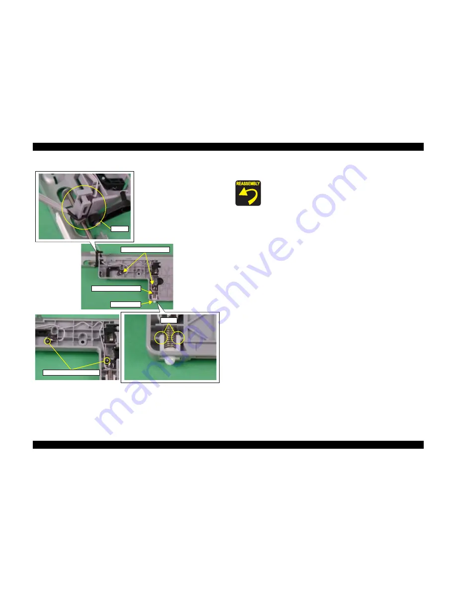
Figure 2-40. "CDR Guide Assy."removal (3)
8.
Remove "Compression Spring, 5.1" and "Lock, Stacker" from "CDR Guide,
Upper".
9.
Release the connector cable of "Star Wheel/CDR Sensor" from the groove of
"CDR Guide, Upper".
Compression Spring, 5.1
Lock, Stacker
Star Wheel/CDR Sensor
Groove
Hooks
Shaft and Positioning Hole
o
When reinstalling "Star Wheel/CDR Sensor",
n
Match the Shaft (x2) of "CDR Guide, Upper" and the
positioning hole of "Star Wheel/CDR Sensor".
n
Mount correctly the connector cable of "Star Wheel/CDR
Sensor" referring to the figure.
o
When reinstalling "CDR Guide, Upper"
n
Make sure that the hooks (x2) of "Lock Stacker" are
properly secured by the tension of "Compression Spring,
5.1".
n
Make sure that "CDR Guide, Upper" is securely secured
with the hooks (x7) of "CDR Guide, Lower" and there is no
gap between "CDR Guide, Upper" and "CDR Guide,
Lower".
o
When reinstalling "CDR Guide Assy.",
n
Place the the connector cable of "Star Wheel/CDR Sensor"
on the red circle position of acetate tape.
n
Place the the connector cable of "Star Wheel/CDR Sensor"
along with "Link, CDR Right" with standing "CDR Tray
Assy." vertically.
n
Install "CDR Guide Assy." in the order of left edge, right
edge and middle.
n
Match the slot (x6) of "CDR Guide Assy." and the ribs (x6)
of "Frame, Main".
n
Check if "Link, CDR Left (Right)" is correctly installed.
n
Check if the connector cable of "Star Wheel/CDR Sensor" is
not interrupting "Link, CDR Right".
n
Check if "Frame, EJ Assy." works with "CDR Guide Assy."
and moves smoothly.
Summary of Contents for R200 - Stylus Photo Color Inkjet Printer
Page 1: ...EPSON StylusPhotoR200 R210 Color Inkjet Printer SEIJ03014 SERVICE MANUAL ...
Page 5: ...Revision Status Revision Issued Date Description A January 29 2004 First Release ...
Page 7: ...C H A P T E R TROUBLESHOOTING ...
Page 30: ...C H A P T E R DISASSEMBLYANDASSEMBLY ...
Page 72: ...C H A P T E R ADJUSTMENT ...
Page 86: ...C H A P T E R MAINTENANCE ...
Page 96: ...C H A P T E R APPENDIX ...
Page 98: ...Model PM G700 Board C546MAIN Rev F Sheet 1 1 ...
Page 99: ...Model PM G700 Board C546PNL Rev A Sheet 1 1 ...
Page 100: ...Model PM G700 Board C528PSH Rev A Sheet 1 1 ...


