EPSON Stylus Photo R200/R210
Revision A
DISASSEMBLY AND ASSEMBLY
Disassembly
45
2.3.7 Board, Main removal
o
External View
Figure 2-12. Board, Main removal
o
Pars/Units which should be removed before removing "Board, Main"
Paper Support Assy./Housing (left/right)/Housing (frame)
/ASF Unit
o
Disassembly Procedure
1.
Disconnect all connector cables from "Board, Main".
CN2
: Power supply connector cable
CN4
: Panel board connector cable
CN5
: CR motor connector cable
CN6
: PF motor connector cable
CN7
: Head FFC
CN8
: Head FFC
CN9
: PE sensor connector cable
CN10
: Interface board connector cable
CN11
: CDR tray sensor cable
CN13
: APG motor connecor cable
CN14
: PG sensor cable
CN15
: CSIC/CR encoder /PW sensor FFC
2.
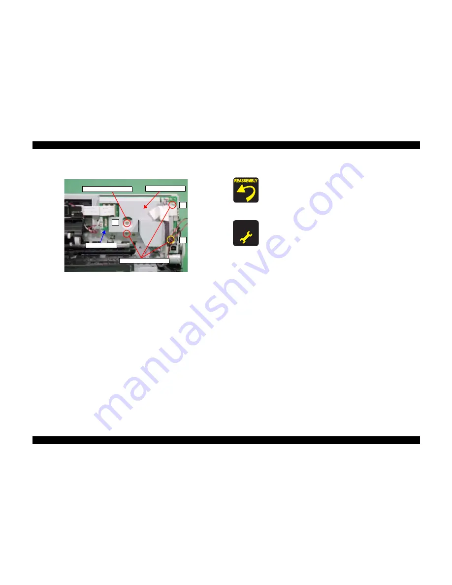
Remove the screws (x4) for securing "Board, Main"with the order in figure, and
remove "Board, Main".
3.
Remove "Shield Plate, M/B" from "Board, M/B".
1
2
3
C.B.S 3x10 (5‑7kgf/cm)
4
C.B.S 3x6 (5‑7kgf/cm)
Board, Main
Shield Plate
,M/B
o
When reinstalling "Board, Main",
n
Make sure that all cables/FFCs are correctly connected to
the appropriciate connector of "Board, Main".
n
Make sure to secure the screws in the order as shown in the
figure.
A D J U S T M E N T
R E Q U I R E D
o
When having replaced "Main Board", implement the
adjustment in the following order. (Refer to Chapter 3
"ADJUSTMENT")
n
When possible to read data from the old board
1.
EEPROM data copy
n
When impossible to read from the old board
1.
Replace "Waste Ink Pads" with new one.
(To count the amount of the waste ink)
2.
Market Setting
3.
USB ID Input
4.
Waste Ink Pad Counter
5.
Head ID Input
6.
First Dot Adjustment
7.
PW Sensor Adjustment
8.
Head Angular Adjustment
9.
Bi-D Adjustment
10. Offset Input for CR Motor Calorific Limitation
Summary of Contents for R200 - Stylus Photo Color Inkjet Printer
Page 1: ...EPSON StylusPhotoR200 R210 Color Inkjet Printer SEIJ03014 SERVICE MANUAL ...
Page 5: ...Revision Status Revision Issued Date Description A January 29 2004 First Release ...
Page 7: ...C H A P T E R TROUBLESHOOTING ...
Page 30: ...C H A P T E R DISASSEMBLYANDASSEMBLY ...
Page 72: ...C H A P T E R ADJUSTMENT ...
Page 86: ...C H A P T E R MAINTENANCE ...
Page 96: ...C H A P T E R APPENDIX ...
Page 98: ...Model PM G700 Board C546MAIN Rev F Sheet 1 1 ...
Page 99: ...Model PM G700 Board C546PNL Rev A Sheet 1 1 ...
Page 100: ...Model PM G700 Board C528PSH Rev A Sheet 1 1 ...


