RTC - 8564 JE/NB
Page - 4
MQ - 322 - 04
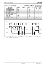
7.2. AC electrical characteristics
∗
If not specifically indicated, GND=0 V, V
DD
=1.8 V to 5.5 V
, Ta=
−
40
°
C to +85
°
C
Parameter Symbol
Condition
Min.
Typ.
Max.
Unit
SCL clock frequency
f
SCL
400
kHz
Start condition set-up time
t
SU; STA
0.6
µ
s
Start condition hold time
t
HD; STA
0.6
µ
s
Data set-up time
t
SU; DAT
100
ns
Data hold time
t
HD; DAT
0
ns
Stop condition set-up time
t
SU; STO
0.6
µ
s
Bus free time between a STOP
and START condition
t
BUF
1.3
µ
s
SCL "L" time
t
LOW
1.3
µ
s
SCL "H" time
t
HIGH
0.6
µ
s
SCL and SDA rise time
tr
0.3
µ
s
SCL and SDA fall time
tf
0.3
µ
s
Tolerance spike time on bus
t
SP
50
ns
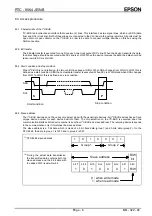
Timing chart
t
HD ; DAT
t
SU ; DAT
t
HD ; STA
t
LOW
t
HIGH
1 / f
SCL
t
r
t
f
t
SU ; STA
SDA
SCL
START
CONDITION
(S)
BIT 7
MSB
(A7)
BIT 6
(A6)
ACK
(A)
Protocol
t
BUF
t
SU ; STO
STOP
CONDITION
(P)
START
CONDITION
(S)
(P)
(A)
t
HD ; STA
t
SU ; STA
(S)
BIT 0
LSB
(R/W)
(S)
t
SP
Note : I
2
C access time between a START and a START condition or between a START and a STOP condition to this
device must be less than one second.


