


Setup & Operation 5. Motion Range
G6 Rev.21
71
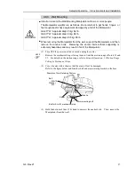
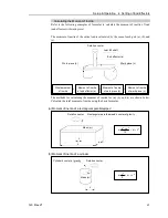
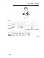
5.2 Motion Range Setting by Mechanical Stops
Mechanical stops physically limit the absolute area that the Manipulator can move.
Both Joints #1 and #2 have threaded holes in the positions corresponding to the angle for
the mechanical stop settings. Install the bolts in the holes corresponding to the angle that
you want to set.
Joints #3 can be set to any length less than the maximum stroke.
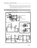
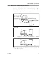
Table Top Mounting
Mechanical stop of Joint #2
(Adjustable)
Mechanical stop of
Joint #1 (Fixed)
Mechanical stop of Joint #3
(Lower limit mechanical stop)
(Do not move the upper
limit mechanical stop.)
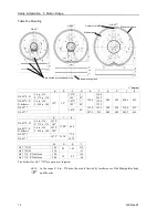
Mechanical stop of
Joint #1 (Adjustable)
Mechanical stop of Joint #2
(Fixed)
Wall Mounting
Mechanical stop of Joint #1 (Fixed)
Mechanical stop of Joint #1 (Adjustable)
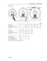
Ceiling Mounting
Mechanical stop of Joint #1 (Fixed)
Mechanical stop of Joint #1 (Adjustable)
* The different mechanical stop positions from Table Top mounting are indicated for Wall
mounting and Ceiling mounting.
Summary of Contents for G6 series
Page 1: ...Rev 21 EM183R3621F SCARA ROBOT G6 series MANIPULATOR MANUAL ...
Page 2: ...MANIPULATOR MANUAL G6 series Rev 21 ...
Page 8: ...vi G6 Rev 21 ...
Page 14: ......
Page 94: ......
Page 216: ...Maintenance 14 Maintenance Parts List 204 G6 Rev 21 ...