


Setup & Operation 2. Specifications
18
G6 Rev.21
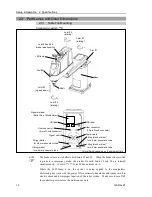
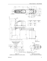
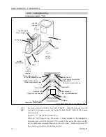
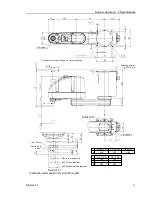
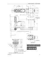
2.3 Part Names and Outer Dimensions
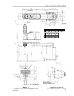
2.3.1 Table Top Mounting
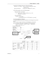
Standard-model G6-***S
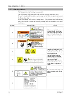
Signature label
(Serial No. of Manipulator)
Signal cable
Power cable
Fitting (black or blue)*
for ø 6 mm pneumatic tube
User connector
(15-pin D-sub connector)
User connector
(9-pin D-sub connector)
CE label
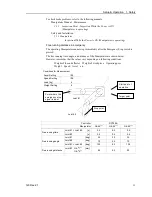
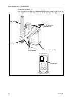
Joint #3 and #4
brake release switch
Joint #1
(rotating)
Joint #2
(rotating)
Joint #3
(up and down)
Joint #4
(rotating)
Arm #1
Arm #2
Base
+
−
+
−
+
−
+
−
Shaft
Fitting (black or blue)*
for ø 4 mm pneumatic tube
Fitting (white)
for ø 6 mm pneumatic tube
Fitting (white)
for ø 4 mm pneumatic tube
LED lamp
UR label
* Color differs depending on the shipment time
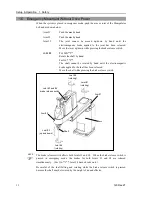
- The brake release switch affects both Joints #3 and #4. When the brake release switch
is pressed in emergency mode, the brakes for both Joints #3 and #4 are released
simultaneously. (For G6-**1**, Joint #4 has no brake on it.)
- While the LED lamp is on, the current is being applied to the manipulator.
Performing any work with the power ON is extremely hazardous and it may result in
electric shock and/or improper function of the robot system. Make sure to turn OFF
the controller power before the maintenance work.
NOTE
Summary of Contents for G6 series
Page 1: ...Rev 21 EM183R3621F SCARA ROBOT G6 series MANIPULATOR MANUAL ...
Page 2: ...MANIPULATOR MANUAL G6 series Rev 21 ...
Page 8: ...vi G6 Rev 21 ...
Page 14: ......
Page 94: ......
Page 216: ...Maintenance 14 Maintenance Parts List 204 G6 Rev 21 ...