


Maintenance 7. Arm #3
142
G6 Rev.21
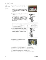
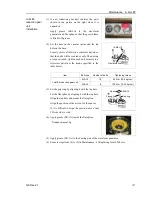
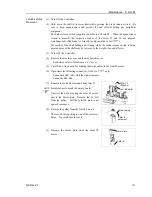
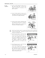
(6) Place the Z belt around the Z1 pulley and the Z2
pulley so that the gear grooves of the belt are fit
into those of the pulleys completely.
Joint #3
motor unit
Z belt
Z2 pulley Z1 pulley
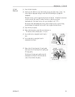
(7) Loosely secure the Joint #3 motor unit to Arm #2.
Loosely secure the Joint #3 motor unit to Arm #2 so that the motor unit can be moved
by hand, and it will not tilt when pulled. If the unit is secured too loose or too tight,
the belt will not have the proper tension.
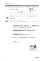
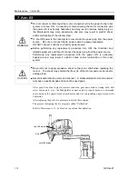
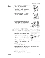
(8) Apply the proper tension to the Z belt, and then
secure the Joint #3 motor unit.
At this point, be careful of the battery board.
To remove the battery board, take out the set
screws with cables connected.
Hexagonal wrench (Stubby type) makes it easier
to tighten / remove screws.
4-M4
×
12
+
Washer
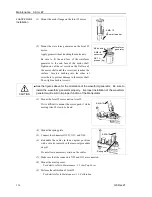
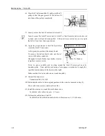
Z belt tension = 80 N (8.2 kgf)
Force gauge
Joint #3
motor unit
To do so, pass a suitable cord or string around the Joint #3 motor unit near its
mounting plate. Then, pull the cord using a force gauge or similar tool to apply the
specified tension shown in the figure on the right.
Make sure that the brake cables do not touch the pulley.
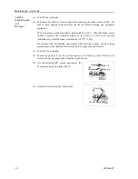
(9) Connect the connectors.
Connectors X231, X31, X63
(10) Re-bundle the cables in their original positions with a wire tie removed in step (5).
Do not allow unnecessary strain on the cables.
(11) Install the arm top cover and the arm bottom cover.
For details, refer to
Maintenance: 3. Covers
.
(12) Perform the calibration of Joint #3.
For details on the calibration method, refer to
Maintenance: 13. Calibration
.
NOTE
Summary of Contents for G6 series
Page 1: ...Rev 21 EM183R3621F SCARA ROBOT G6 series MANIPULATOR MANUAL ...
Page 2: ...MANIPULATOR MANUAL G6 series Rev 21 ...
Page 8: ...vi G6 Rev 21 ...
Page 14: ......
Page 94: ......
Page 216: ...Maintenance 14 Maintenance Parts List 204 G6 Rev 21 ...