


Maintenance 8. Arm #4
158
G6 Rev.21
U2 belt
Removal
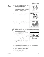
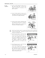
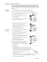
(1) Turn ON the Controller.
(2) Push down the shaft to its lower limit while pressing the brake release switch. Be
sure to keep enough space and prevent the end effector hitting any peripheral
equipment.
The brake release switch is applied to both Joints #3 and #4. When the brake release
switch is pressed, the respective brakes for Joints #3 and #4 are released
simultaneously. (The brake for Joint #4 is only installed to G6-**3**.)
Be careful of the shaft falling and rotating while the brake release switch is being
pressed because the shaft may be lowered by the weight of an end effector.
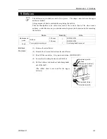
(3) Turn OFF the Controller.
(4) Remove the arm top cover and the arm bottom cover.
For details, refer to
Maintenance: 3. Covers
.
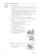
(5) Cut off the wire tie used for binding the motor cables to the Joint #3 motor.
(6) Disconnect the following connectors.
Connectors X231, X31 (Hold the claw to remove.)
Connector X63, X32
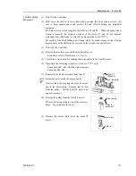
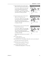
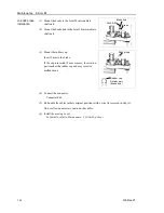
(7) Remove the Joint #3 motor unit from Arm #2.
Remove the bolts securing the Joint #3 motor
plate. Remove the Z belt from the pulley.
Pull the Joint #3 motor unit upward to remove.
Pulley
Z belt
4-M4
×
12
+
Washer
Joint #3
motor unit
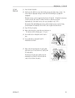
(8) Loosen the bolts securing the Joint #4 motor unit.
6-M4
×
12
+
Washer
Joint #4
intermediate
shaft unit
Joint #4
motor unit
(9) Loosen the bolts securing the Joint #4
intermediate shaft unit.
Summary of Contents for G6 series
Page 1: ...Rev 21 EM183R3621F SCARA ROBOT G6 series MANIPULATOR MANUAL ...
Page 2: ...MANIPULATOR MANUAL G6 series Rev 21 ...
Page 8: ...vi G6 Rev 21 ...
Page 14: ......
Page 94: ......
Page 216: ...Maintenance 14 Maintenance Parts List 204 G6 Rev 21 ...