


Maintenance 4. Cable
G6 Rev.21
117
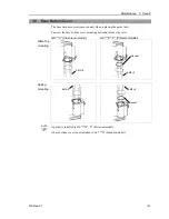
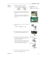
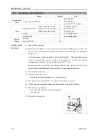
(13) Mount the saddle part to the spring plate.
2-M5
×
10
Saddle part
(14) Connect the connectors and the ground wire.
For details, refer to
Maintenance: 4.2 Wiring Diagrams
.
(15) Bind the excess cables with a wire tie.
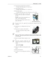
(16) Connect the D-sub cable, air tubes, and connector
of the brake release switch cable to the user plate.
D-sub cable
Air tube
Brake release switch cable
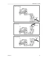
(17) Mount the user plate to the Arm #2 cover.
For details of user plate installation, refer to
Maintenance 3.6 User Plate
.
(18) Set and secure the Arm #2 cover without the cables being stuck.
For details, refer to
Maintenance: 3.1 Arm Top Cover
.
(19) Mount the arm caps and side covers for Arm #1.
For details, refer to
Maintenance: 3.3 Arm #1 Cover
.
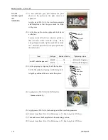
(20) Remove the conector plate mounted loosely in the step (8) and remove the spare battery
in theXB11. Then, mount the connector plate.
In this replacement method, calibration is not needed.
However, perform the calibration if it is required.
NOTE
Summary of Contents for G6 series
Page 1: ...Rev 21 EM183R3621F SCARA ROBOT G6 series MANIPULATOR MANUAL ...
Page 2: ...MANIPULATOR MANUAL G6 series Rev 21 ...
Page 8: ...vi G6 Rev 21 ...
Page 14: ......
Page 94: ......
Page 216: ...Maintenance 14 Maintenance Parts List 204 G6 Rev 21 ...