


Maintenance 6. Arm #2
G3 Rev.14
113
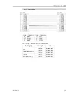
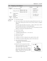
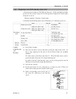
6.1 Replacing Joint #2 Motor
Name
Quantity
Note
Maintenance
Parts
AC Servo Motor (150W)
1
R13B000615
Tools
Hexagonal wrench
width across flats: 2 mm
1
For M4 set screw
width across flats: 3 mm
1
For M4 screw
width across flats: 4 mm
1
For M5 screw
Torque wrench
1
Nippers
1
For cutting wire tie
Wiping cloth
1
For wiping grease
Material
Wire tie
4
Grease
Grease (SK-2)
3 g
Joint #2 motor
Removal
(1) Turn ON the Controller.
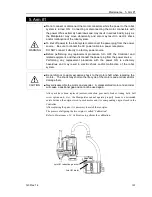
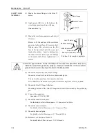
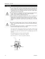
(2) Push down the shaft to its lower limit while pressing the brake release switch. Be
sure to keep enough space and prevent the end effector hitting any peripheral
equipment.
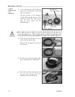
The brake release switch affects only Joint #3. When the brake release switch is
pressed, the brake for the Joint #3 is released simultaneously.
Be careful of the shaft while the brake release switch is being pressed because the
shaft may be lowered by the weight of an end effector.
(3) Turn OFF the Controller.
(4) Remove the arm top cover.
For details, refer to
Maintenance: 3.1 Arm Top Cover
.
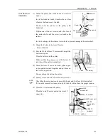
(5) Remove the battery board.
(6) Remove the user plate.
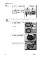
(7) Cut off the wire tie used for binding the cables connected to the user cable.
(8) Cut off the wire tie used for binding the motor cables to the Joint #2 motor.
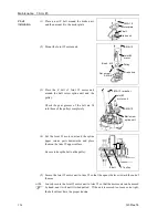
(9) Disconnect the following connectors.
Connectors X221, X21 (Hold the claw to remove.)
Connector X62
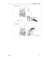
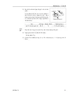
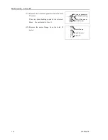
(10) Remove the Joint #2 motor unit from Arm #2.
If the motor cannot be removed easily, pull it out
while moving Arm #2 slowly by hand.
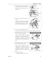
Also, the motor flange touches the intermediate
pulley and you cannot pull the motor straight
upward. Therefore, tip the motor and pull it
avoiding he intermediate pulley.
3-M4
×
12
Summary of Contents for G3 Series
Page 1: ...Rev 14 EM183R3623F SCARA ROBOT G3 series MANIPULATOR MANUAL ...
Page 2: ...MANIPULATOR MANUAL G3 series Rev 14 ...
Page 8: ...vi G3 Rev 14 ...
Page 14: ......
Page 84: ...Setup Operation 5 Motion Range 72 G3 Rev 14 ...
Page 86: ...74 ...
Page 200: ...Maintenance 15 Maintenance Parts List 188 G3 Rev 14 ...


