FX-2180 Service Manual
Disassembly and Assembly
Rev. A
4-18
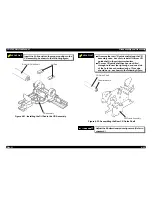
4.2.9.5 Disassembling the Right Frame Assembly
1.
Remove one CBS screw (3
×
6) and one CBS screw (3
×
8) securing
the right sub frame. (The bold line in the illustration is the right sub
frame.)
2.
Remove the right sub frame from the right frame.
R i g h t S u b F r a m e
C B S ( 3 x 6 )
C B S ( 3 x 8 )
Figure 4-21. Removing the Right Sub Frame
CHECK POINT
9
The tightening torque for the CBS screws (3
××
6)
and (3
××
8) : 0.78
∼∼
0.98 Nm (8
∼∼
10 Kgf-cm)
The tightening torque for the hexagon nut : 1.18
∼∼
1.37 Nm (12
∼∼
14 Kgf-cm)
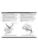
Mount the 11 parts above on the right frame
assembly, as shown in the following figures.
C o m p r e s s i o n S p r i n g 2 0 0 a n d
P l a i n W a s h e r
S p u r G e a r 3 4 . 5
S p u r G e a r 2 1
S p u r G e a r 3 4 . 5
C o m b i n a t i o n G e a r 8 / 3 1 . 5
I n t e r m i t t e n t G e a r
S p u r G e a r 2 7
S p u r G e a r 3 4
Figure 4-22. Engaging Gears 1
$'-8670(17
Adjust the Bi-directional print alignment. (Refer to
chapter 4.)
Summary of Contents for FX-2180 - Impact Printer
Page 1: ...EPSON EPSON EPSON France S A SERVICE MANUAL FX 2180 PRODUIT ...
Page 2: ...6 59 0 18 3LQ PSDFW RW 3ULQWHU EPSON FX 2180 4009047 ...
Page 6: ...REVISION STATUS Rev Date Page s Contents A 1998 04 02 All First release ...
Page 11: ...PRODUCT DESCRIPTIONS 3 7 5 ...
Page 24: ...OPERATING PRINCIPLES 3 7 5 ...
Page 28: ...TROUBLESHOOTING 3 7 5 ...
Page 43: ...DISASSEMBLY AND ASSEMBLY 3 7 5 ...
Page 76: ...ADJUSTMENT 3 7 5 ...
Page 86: ...MAINTENANCE 3 7 5 ...
Page 89: ...APPENDIX 3 7 5 ...
Page 101: ......
Page 104: ......

