background image

FX-2180 Service Manual

Disassembly and Assembly

Rev. A

4-13

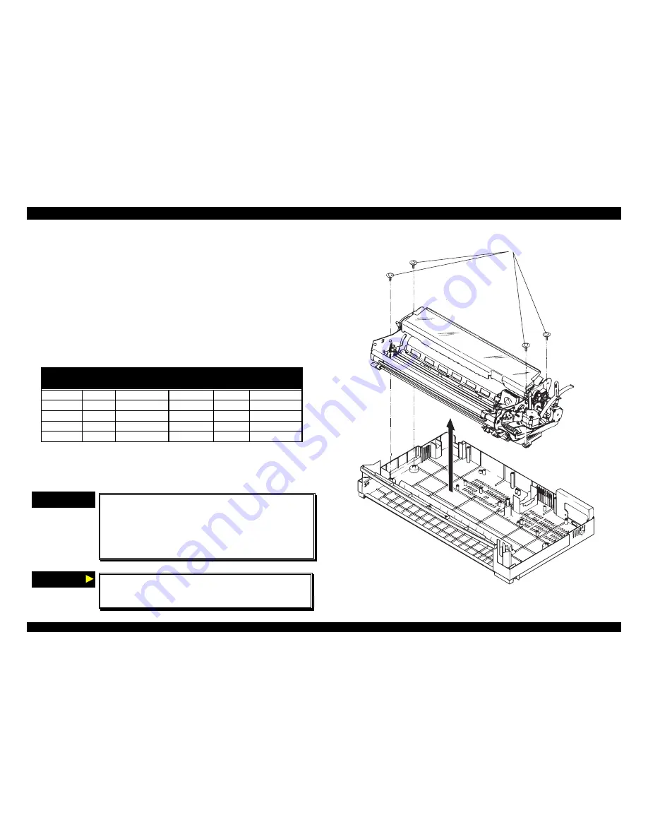
4.2.9  Removing the Printer Mechanism

1. 

Remove the printer cover, the rear / front edge guide assemblies, front
cover, paper eject assembly, and rear tractor unit. (Refer to Section
4.2.1.)

2. 

Remove the panel board assembly. (Refer to Section 4.2.2.)

3. 

Remove the upper housing assembly. (Refer to Section 4.2.7.)

4. 

Remove three CBS screws (3 

×

 4) securing the upper shield plate to

the printer mechanism and the upper I/F grounding plate on the main
board assembly.

5. 

Remove four printer mechanism mounting screws securing the printer
mechanism.

6. 

Disconnect the following connectors on the main board assembly.

Table 4-7. Connectors’ List

Number

Pin

Connector

Color

Number

Pin

Connector

Color

CN4

3

white

CN5

3

black

CN6

2

white

CN7

4

gray

CN8

18

gray

CN9

16

gray

CN10

4

white

CN11

5

white

CN12

4

white

CN13

4

black

Note : Disconnect the cable for CN10 and CN11 after releasing the
connector locks by pulling up.

7. 

Remove the printer mechanism.

CHECK POINT

9

„

„

Notice the connector for cables CN10 and CN11,
and align the red colored cable to pin 1 of the
connector.

„

„

The tightening torque for the printer mechanism
mounting screws : 0.78 

∼∼

 0.98 Nm (10 

∼∼

 12 Kgf-

cm)

$'-8670(17

If remove or replace the printer mechanism once,
adjust the bi-directional print alignment and reset
the TPE level. (Refer to Section Chapter4.)

P r i t n e r   M e c h a n i s m   M o u n t i n g   S c r e w s

Figure 4-15. Removing the Printer Mechanism

Summary of Contents for FX-2180 - Impact Printer

Page 1: ...EPSON EPSON EPSON France S A SERVICE MANUAL FX 2180 PRODUIT ...

Page 2: ...6 59 0 18 3LQ PSDFW RW 3ULQWHU EPSON FX 2180 4009047 ...

Page 3: ...e contents of this manual However should any errors be deteced SEIKO EPSON would greatly appreciate being informed of them The above not withstanding SEIKO EPSON CORPORATION can assume no responsibility for any errors in this manual or the consequences thereof EPSON is a registered trademark of SEIKO EPSON CORPORATION General Notice Other product names used herein are for identification purpose on...

Page 4: ...NOT CONNECT THE UNIT TO A POWER SOURCE UNTIL INSTRUCTED TO DO SO WHEN THE POWER SUPPLY CABLE MUST BE CONNECTED USE EXTREME CAUTION IN WORKING ON POWER SUPPLY AND OTHER ELECTRONIC COMPONENTS WARNING 1 REPAIRS ON EPSON PRODUCT SHOULD BE PERFORMED ONLY BY AN EPSON CERTIFIED REPAIR TECHNICIAN 2 MAKE CERTAIN THAT THE SOURCE VOLTAGES IS THE SAME AS THE RATED VOLTAGE LISTED ON THE SERIAL NUMBER RATING PL...

Page 5: ...the theory of electrical and mechanical operations of the product CHAPTER 3 TROUBLESHOOTING Provides the step by step procedures for troubleshooting CHAPTER 4 DISASSEMBLY AND ASSEMBLY Describes the step by step procedures for disassembling and assembling the product CHAPTER 5 ADJUSTMENTS Provides Epson approved methods for adjustment CHAPTER 6 MAINTENANCE Provides preventive maintenance procedures...

Page 6: ...REVISION STATUS Rev Date Page s Contents A 1998 04 02 All First release ...

Page 7: ...Operation at power on 1 10 1 3 1 1 Self Test 1 10 1 3 1 2 Default Setting 1 10 1 3 1 3 Data Dump 1 11 1 3 1 4 Clear EEPROM 1 11 1 3 1 5 Clear EEPROM for driving line counter for ribbon changing timing 1 11 1 3 1 6 Alternate copy mode 1 11 1 3 1 7 Bi D Adjustment 1 12 1 4 CONSUMABLES OPTIONS 1 12 1 4 1 Consumables 1 12 1 4 2 Options 1 12 OPERATING PRINCIPLES 2 1 OVERVIEW 2 1 2 1 1 Printer Mechanism...

Page 8: ... Motors 3 3 3 2 4 Error Codes with Indications and Buzzer 3 3 3 3 UNIT LEVEL TROUBLESHOOTING 3 4 3 4 REPAIRING THE POWER SUPPLY BOARD 3 7 3 5 REPAIRING C244 MAIN BOARD ASSEMBLY 3 9 3 6 REPAIRING THE PRINTER MECHANISM 3 12 DISASSEMBLY AND ASSEMBLY 4 1 OVERVIEW 4 1 4 1 1 Precaution 4 1 4 1 2 Tools 4 1 4 1 3 Service Check After Repair 4 2 4 1 4 Specifications for Screws 4 3 4 2 DISASSEMBLY AND ASSEMB...

Page 9: ...ght Frame Assembly 4 18 4 2 9 6 Removing the Left Frame Assembly 4 20 4 2 9 7 Removing the Ribbon Drive RD Assembly 4 21 4 2 9 8 Removing the CR Assembly 4 22 4 2 9 9 Removing the Rear PE Sensor Assembly 4 24 4 2 9 10 Removing the Front PE Sensor Assembly 4 24 4 2 9 11 Removing the Main Board Assembly 4 25 4 2 9 12 Removing the Power Supply board Assembly 4 26 4 2 10 Disassembly and Assembly of CS...

Page 10: ...nt Alignment Bi d Adjustment 5 4 5 2 2 1 Bi d Adjustment using the Setting Diskette 5 4 5 2 2 2 Bi D Adjustment from the Control Panel 5 6 5 2 3 Factory Settings 5 7 5 2 4 TPE Level Reset 5 8 MAINTENANCE 6 1 PREVENTIVE MAINTENANCE 6 1 6 2 APPLYING LUBRICATION 6 1 APPENDIX 7 1 CONNECTOR SUMMARY 7 1 7 2 CIRCUIT BOARD COMPONENT LAYOUT 7 5 7 3 EXPLODED DIAGRAMS 7 7 7 4 CIRCUIT BOARD DIAGRAMS 7 11 ...

Page 11: ...PRODUCT DESCRIPTIONS 3 7 5 ...

Page 12: ...2 244 condensed 20 cpi 272 380 330 284 Draft emphasized 10 cpi 136 190 165 142 NLQ 10 cpi 136 95 82 71 12 cpi 163 114 99 85 15 cpi 204 94 71 31 When the power supply voltage drops to the lower limit the printer stops printing and then starts printing remain on that line again more slowly than before When the head temperature rises to the upper limit the printer stops printing When the head tempera...

Page 13: ...r more 4 2mm or more Notice Maximum horizontal printable area is 345 2mm Envelope Printable Area PW LM RM PL TM BM Figure 1 2 Printable Area Envelope Table 1 4 Printable Area Envelope Envelope Width PW Refer to Paper Media Length PL Refer to Paper Media Left margin LM 3mm or more Right margin RM 3mm or more Top margin TM 4 2mm or more Bottom margin BM 4 2mm or more Continuous paper PW LM RM PL TM ...

Page 14: ...r Paper path Manual insertion Front Rear in Top out CSF Rear in Top out Tractor Front Rear bottom in Top out Feed speed Normal 61ms 1 6inch feed 0 127MPS or 5 0IPS continuous Copy mode 83ms 1 6inch feed 0 078MPS or 3 1IPS continuous PAPER MEDIA Single sheet Table 1 7 Paper Specification Single sheet Front entry Rear entry Minimum Maximum Minimum Maximum Width inch mm 3 9 100 16 5 420 3 9 100 16 5 ...

Page 15: ...led paper Not curled Not folded Not crumpled Jointing Line glue at the top or one side of form Line glue at the top of form Envelope Table 1 9 Paper Specification Multi part sheet Front entry Rear entry Min Max Minimum Maximum Envelope No 6 Width inch mm 6 5 165 Length inch mm 3 9 92 Envelope No 10 Width inch mm 9 5 241 Length inch mm 4 1 105 Total Thickness inch mm 0 0063 0 16 0 020 0 52 Weight g...

Page 16: ...nal 6 copies paper is available in pull tractor feed Continuous paper with labels Table 1 11 Paper Specification Continuous paper with Labels Front entry Rear entry Bottom entry Min Max Min Max Min Max Label size inch mm 15 16 2 5 23 8 63 5 15 16 2 5 23 8 63 5 Width inch mm 4 101 6 16 406 4 4 101 6 16 406 4 Length inch mm 4 101 6 22 558 8 4 101 6 22 558 8 Base sheet Thickness inch mm 0 0028 0 07 0...

Page 17: ... Input voltage range AC 99 132V Rated frequency range 50 60Hz Input frequency range 49 5 60 5Hz Rated current 1 0A max 1 8A Power consumption Approx 46W ISO IEC10561 Letter pattern Energy Star program compliant Insulation resistance 10MΩ min AC line Chassis 500V Dielectric strength AC1000V rms 1 minute or AC1200V rms 1 second AC line Chassis 230V version Rated voltage AC220 240V Input voltage rang...

Page 18: ... CSA C108 8 class B 230V version Safety standard EN60950 TÜV NEMKO EMI EN55022 CISPR pub 22 class B AS NZS 3548 class B UPS version Safety standard UL1950 CSA C22 2 No 950 EN60950 TÜV NEMKO EMI FCC part 15 subpart B class B CSA C108 8 class B EN55022 CISPR pub 22 class B AS NZS 3548 class B CE MARKING 230V version UPS version Low Voltage Directive 73 23 EEC EN60950 EMC Directive 89 336 EEC EN55022...

Page 19: ...between on line and off line Hold it down over 3 seconds when the printer is in stand by condition and the Micro Adjust functions is enabled If the switch is pressed again this function is disabled Load Eject Pressing it loads cut sheet or continuous paper when the printer is out of paper Pressing it eject cut sheet to the stacker or continuous paper to the paper park LF FF Pressing it shortly exe...

Page 20: ...s selected Only left LED is on when CSF bin 2 is selected Both LEDs are on when Card mode is selected Both LEDs blink when continuous paper is in the Tear Off position Both LEDs are off when continuous paper is out of the Tear Off position Font Green The font LEDs consist of two LEDs The current using font is shown by these two LEDs on off combinations Pitch Green The pitch LEDs consist of three L...

Page 21: ...ter once Draft Self Test Turning on the printer while holding down FF LF switch the printer prints self test pattern with NLQ fonts If desire to stop it turn off the printer once 1 3 1 2 Default Setting Several printer settings loaded at power on can be changed in this operation Setting Method The setting method is shown in the flowchart as following START Holding down Pitch switch turn on Languag...

Page 22: ...ding down Font and Tear off Bin switches The data of EEPROM Area 1 are reset to the factory setting without driving line count driving hour driving line counter for ribbon changing timing starting year starting month and starting date Refer to the FX 2180 Specifications CAUTION This printer always stores driving line count driving hour driving line counter for ribbon changing timing starting year ...

Page 23: ... value NLQ Bi D adjustment finish Turn off the printer END YES NO Figure 1 8 Bi D Adjustment Method CAUTION Bi D adjust value is not reset by clearing EEPROM 1 4 CONSUMABLES OPTIONS 1 4 1 Consumables Ribbon cartridge S015086 Ribbon pack S010033 1 4 2 Options High capacity cut sheet feeder bin 1 C80673 Second bin cut sheet feeder C80674 Pull tractor unit C80032 Roll paper holder 8310 Serial I F car...

Page 24: ...OPERATING PRINCIPLES 3 7 5 ...

Page 25: ...ic with CR guide shaft center and PG adjust lever It makes the printhead associate with platen or keep away from platen causing from PG adjust lever position Paper feed mechanism This mechanism consists of paper feed motor PF Motor rear front tractors platen and etc This mechanism picks up the cut sheet paper feed the cut sheet paper or continuous paper to the printhead to print paper by PF Motor ...

Page 26: ... produces a stepped down 35VDC voltage The 5VDC is generated and stabled by feeding the 35VDC voltage through the 5VDC power supply circuit IC As this power supply circuit composed of an ZC RCC zero cross ringing choke converter it realizes to the circuit high stability efficiency and portability This circuit provides the power switch operate switch in the secondary circuit system The operate swit...

Page 27: ... l e l I F T y p e B I F 5 V G L 3 5 V G P I C 2 I C 1 E 0 5 B 5 0 T M P 9 6 C 1 4 1 B F Q 2 Q 1 9 I C 1 2 S L A 7 0 2 4 M U D N 2 9 1 7 E B I C 8 I C 1 5 D a t a B u s A d d r e s s B u s I C 3 I C 5 P S C P W D N P o w e r S u p p l y B o a r d I C 9 Figure 2 3 Control circuit Block Diagram The functions of main components of control circuit on C244MAIN board are shown on the following table Tab...

Page 28: ...TROUBLESHOOTING 3 7 5 ...

Page 29: ...d It is easy to check if a printhead is defective or not Referring to the following table and figure measure the printhead coil resistance and check if it is correct Table 3 1 Printhead coil Resistance Test Points Common Pin No Refer to the following figure Test Pin No Refer to the following figure Test Method Set meter to ohms Disconnect the printhead after the printer is powered off Place one le...

Page 30: ...4 A Place one lead on pin 1 and the other lead on pin 2 and check the voltage while inserting and removing paper between the detector Open 0V No paper Short 5V Paper loaded Table 3 3 Detector Test Point continue Detector CN No Test Pin No Test Method Set Meter to DC Voltage Meter Reading CN12 Release Detector 1 2 1 Release 1 2 GND 3 Release 2 4 GND Place one lead on pin 1 and the other lead on pin...

Page 31: ...o CN11 Com mon Pin No 5 Test Pin No 1 2 3 4 Test Method Same as for the PF Motor Place one lead on pin 5 and the other lead on each of 4 pins Meter Reading 2 7 Ω 10 per phase at 25 C 3 2 4 Error Codes with Indications and Buzzer Table 3 5 Error Codes with Indications and Buzzer Indicators Error Condition Pause Paper Out Tear Off Bin Pitch Font Buzzer Paper out On On 3 Paper jam Paper ejected in co...

Page 32: ...g some dots are not printing Flowchart 4 The repair procedure flowcharts use the following symbols START Start Processing Forwarding to another item Decision Branching END Return to the strat of the item END Figure 3 2 Flowchart Symbols 1 Abnormal CR Operation START Dose the CR motor rotates when printer is power on Is CN11 connected correctly Connect CN11 correctly Check the motor coil resistance...

Page 33: ...ard Clear the jam Is the problem solved END YES Dose the Front detector work correctly YES YES NO YES Replace the detector Is the problem solved END Connect them correctly Is the problem solved END Replace the C244MAIN board YES NO YES NO NO YES YES NO NO YES YES NO NO YES YES NO YES NO Figure 3 4 Flowchart 2 1 2 Abnormal Paper Feed Operation 2 START END Is paper ejected automatically after loadin...

Page 34: ... self test printed correctly Check the data from host PC using Hex dump function Are all dots printed correctly Is any dot missing Are all LEDs blinking Check printhead coil resistance Refer to Table 3 1 Replace the printhead Is the printhead OK Check the printhead driver motor drivers and power supply board Is head FFC connected correctly Connect the FFC correctly Is the problem solved END Is the...

Page 35: ... to the unit level including all servicers in the U S can ignore this section Table 3 7 Repairing the Power Supply Board Problem Cause Checkpoint Solution 35V and 5V lines are not output when the printer is power on The diode bridge DB1 is failure Measure the DC voltage between the pin 3 and 4 of DB1 Replace DB1 The transformer T1 coil is open Measure the resistance of T1 coils at pin 12 15 9 11 7...

Page 36: ... waveform at pin 8 of IC51 Figure 3 10 Waveform 3 Replace IC51 Q51 is failure Check the waveform at COLLECTOR of Q51 Figure 3 11 Waveform 4 Replace Q51 L51 is failure Check the resistance between terminals of L51 Replace L51 The PWDN signal is constantly HIGH IC51 is failure Check whether the voltage of pin 6 is more than 1 3V or not If the voltage is more than 1 3V IC51 is failure Replace IC51 ...

Page 37: ...Problem Cause Checkpoint Solution The printer dose not operate at all Reset IC15 is defective Check the voltage waveforms of the VCC signal CH1 IC15 pin 7 and RESET signal CH2 IC15 pin 5 when the printer is turned on CH 1 CH 2 Figure 3 12 Waveform 5 Replace the main board or IC15 Table 3 11 Repairing C244 MAIN Board Assembly Continued Problem Cause Checkpoint Solution The printer dose not operate ...

Page 38: ... output signals at pins 62 63 64 and 65 of the IC1 If the output signal is not correct replace the main board Table 3 13 Repairing C244 MAIN Board Assembly Continued Problem Cause Checkpoint Solution Paper feed is abnormal IC1 IC2 or IC12 is defective Check the input signal waveforms CH 1 at pins 26 and 43 of IC12 Check the output signal waveforms CH 2 at pins 3 6 18 and 21 of IC12 CH 1 CH 2 Figur...

Page 39: ...ls to print IC1 or head drive transistor Q2 Q19 is defective Check the input signal waveform CH 1 at BASE of each transistor Check the output signal waveform CH 2 at COLLECTOR of each transistor CH 1 CH 2 Figure 3 18 Waveform 9 If the input signal is not correct replace the main board If the output signal is not correct replace the transistor or the main board ...

Page 40: ... board Check CN11 Connect CN11 correctly CR motor rotates when the printer is turned on But the CR unit dose not move The timing belt comes off from the pinion of CR motor Check the timing belt Replace the timing belt CR unit moves slightly and then stops Platen gap is too narrow Check CR unit by moving it smoothly by hand Confirm the platen gap Adjust platen gap if narrow Table 3 16 Repairing the...

Page 41: ...he printhead is failure Check if the tip of the dot wire is worn Replace the printhead The platen gap is too wide Check the platen gap Refer to Chapter 5 Adjust platen gap properly Table 3 18 Repairing the Printer Mechanism Continued Problem Symptom Cause Checkpoint Solution Paper feed is abnormal PF motor dose not rotate at all PF motor is defective Measure the coil resistance of PF motor Approx ...

Page 42: ...ng a multimeter Replace the FFC TOP detector is defective Check TOP detector Refer to Table 3 2 Replace TOP detector Table 3 20 Repairing the Printer Mechanism Continued Problem Symptom Cause Checkpoint Solution Paper feed is abnormal Cut sheet paper is loaded CN12 is not connected correctly Check the connection Connect CN12 correctly correctly but continuous paper is not loaded at all Release det...

Page 43: ...DISASSEMBLY AND ASSEMBLY 3 7 5 ...

Page 44: ...power socket CAUTION To maintain efficient printer operation Use only recommended tools for maintenance work Use only recommended lubricants and adhesives Refer to Chapter 6 Adjust the printer only in the manner described in this manual 4 1 2 Tools The following tables list the tools recommended for disassembling assembling or adjusting the printer Use only tools that meet these specifications Tab...

Page 45: ...ath Is the type of paper in the printer feeding smoothly Checked Not necessary Is the tractor feeding paper correctly Checked Not necessary Is the paper path clear of all obstructions Checked Not necessary Is the platen free of damage Checked Not necessary Table 4 4 Inspection Check List for the Repaired Printer 2 Category Components Item Check Printer unit Ribbon mask Is the ribbon mask free of d...

Page 46: ...on Part name CPS Cross recessed pan head S tight screw CBB Cross recessed bind head B tight screw CBS Cross recessed bind head S tight screw CBN Cross recessed bind head N tight screw CBC Cross recessed bind head C lamitite screw CBA Cross recessed bind head A lamitite screw CB O Cross recessed bind head with outside toothed lock washer Table 4 6 Screw types Cross recessed head Bind Normal Top Sid...

Page 47: ...paired wipe the surface of the paper width PW sensor assembly with a soft cloth and keep it clean to avoid abnormal operation If the surface is dirty from any adhering material sensor sensitivity goes down and operation is not correct The flowchart below shows the order to disassemble the printer START Disconnect the printer s power cord and interface cable Preparation for Disassembly Removing the...

Page 48: ...actor assembly Ribbon cartridge CAUTION Remove the paper eject cover and the front rear tractor assembly by pushing to release the hooks at both sides When remount them be sure the hooks on the projecting parts F r o n t E d g e G u i d e A s s e m b l y F r o n t C o v e r F r o n t T r a c t o r U n i t R e a r T r a c t o r U n i t P a p e r E j e c t A s s e m b l y R e a r E d g e G u i d e A...

Page 49: ...e C165 PNL board assembly 4 Remove the panel board assembly from the upper housing assembly C N 1 C N 2 L e f t C l i p Figure 4 3 Remove the Panel Board Assembly CHECK POINT 9 Before disconnecting the FFC from CN1 slide the lock cover for CN1 as shown in Figure 4 4 and release the FFC from CN1 After reconnecting the FFC for CN1 lock the lock cover The FFC must be connected properly as shown in fo...

Page 50: ...disconnect the narrow FFC from the connector on the CR cover C B S 3 x 1 0 P r i n t h e a d F F C s C R A s s e m b l y Figure 4 5 Removing the Printhead CHECK POINT 9 The FFC must be connected properly as shown in the following figure The tightening torque for the screws 0 59 0 78 Nm 6 8 Kgf cm 8670 17 Adjust the platen gap Refer to Chapter 5 F F C s f o r P r i n t h e a d D i r e c t i o n i n...

Page 51: ...r to Section 4 2 1 2 Disconnect the connector cable for the HP sensor 3 Remove the HP sensor by pushing up and releasing the 2 clips at the bottom of the HP sensor from the front paper entrance CHECK POINT 9 Notice the direction for mounting the HP sensor Refer to the following figure 2 C l i p s s e c u r i n g t h e H P s e n s o r Figure 4 7 Removing the HP Sensor ...

Page 52: ...e 4 8 Removing the PW Sensor Assembly 8670 17 Replacing the PW sensor assembly reset the TPE level Refer to Chapter 5 CHECK POINT 9 Mount the PW sensor assembly onto the ribbon mask holder groove aligning the bottom line of micro photo sensor to the bottom line of the groove Whenever you remove the PW sensor assembly clean the surface of the sensor by wiping it with a soft material If the surface ...

Page 53: ...nthead to the right edge 5 Pull the left edge of the platen assembly upward by tilting it backward and then pull up the right edge of the platen assembly Figure 4 11 Removing the platen Assembly CHECK POINT 9 Before installing the platen assembly into the printer mechanism move the printhead to the right edge of the CR shaft and set the release lever to the tractor position This pre assembly opera...

Page 54: ... Section 4 2 2 3 Remove four CBB screws 4 4 securing the upper housing assembly 4 Remove the platen knob 5 Lift up the front side of the housing assembly by releasing 2 hooks from the holes locates on the right and left of the front bottom side Figure 4 12 Releasing the Upper Housing Assembly Hooks 6 Remove the upper housing assembly Figure 4 13 Removing the Upper Housing Assembly CHECK POINT 9 Th...

Page 55: ...e the panel board assembly Refer to Section 4 2 2 3 Turn the upper housing assembly over and remove the case open sensor assembly by loosening one CBB screw 3 8 securing the sensor holder to the upper housing assembly C B B S c r e w 3 x 8 F Z n C B S c r e w 2 x 8 F N i S e n s o r H o l d e r C a s e O p e n S e n s o r A s s e m b l y U p p e r H o u s i n g A s s e m b l y Figure 4 14 Removing...

Page 56: ...ors on the main board assembly Table 4 7 Connectors List Number Pin Connector Color Number Pin Connector Color CN4 3 white CN5 3 black CN6 2 white CN7 4 gray CN8 18 gray CN9 16 gray CN10 4 white CN11 5 white CN12 4 white CN13 4 black Note Disconnect the cable for CN10 and CN11 after releasing the connector locks by pulling up 7 Remove the printer mechanism CHECK POINT 9 Notice the connector for ca...

Page 57: ...leasing the extension spring 15 7 then disengage the timing belt from the CR motor Assembly 6 Remove the two CR mounting screws securing the CR motor assembly 7 Disconnect the cable for CN11 from the main board 8 Remove the CR motor assembly from the printer mechanism C R M o u n t i n g S c r e w E x t e n s i o n S p r i n g 1 5 7 C R M o t o r A s s e m b l y Figure 4 16 Removing the CR Motor A...

Page 58: ...3 6 and screw 3 10 securing the PF motor 7 Disconnect connector CN10 from the main board assembly 8 Remove the PF motor from the right sub frame 9 Return the release lever to the friction feed mode CHECK POINT 9 Before attaching the PF motor to the proper position on the right sub frame set the release lever to the pull tractor mode full release position The CB screw 3 8 is used to secure the uppe...

Page 59: ...ove one hexagon nut M4 securing the PG sensor assembly to the right frame assembly H e x a g o n N u t P G S e n s o r A s s e m b l y Figure 4 18 Removing the PG Sensor Assembly CHECK POINT 9 When the sensors are mounted to the PG sensor holder be sure to mount the while connector s sensor in the upper position as shown in the following figure When securing the shaft push the front CR guide shaft...

Page 60: ...move the CR motor assembly Refer to Section 4 2 9 1 6 Remove the PF motor Refer to Section 4 2 9 2 7 Remove the PG sensor assembly Refer to Section 4 2 9 3 8 Remove the hexagon nut M4 securing the gap adjust lever Then remove the lever from the right frame assembly 9 Remove one CBS screws 3 6 securing the platen cover to the right frame assembly 10 Remove two CBS screws 3 6 securing the right fram...

Page 61: ...HECK POINT 9 The tightening torque for the CBS screws 3 6 and 3 8 0 78 0 98 Nm 8 10 Kgf cm The tightening torque for the hexagon nut 1 18 1 37 Nm 12 14 Kgf cm Mount the 11 parts above on the right frame assembly as shown in the following figures C o m p r e s s i o n S p r i n g 2 0 0 a n d P l a i n W a s h e r S p u r G e a r 3 4 5 S p u r G e a r 2 1 S p u r G e a r 3 4 5 C o m b i n a t i o n ...

Page 62: ...nd release transmission lever to the tractor clutch cam notice the points in the following figure R e l e a s e L e v e r R e l e a s e T r a n s m i s s i o n L e v e r I n t e r m i t t e n t G e a r Figure 4 23 Engaging Gears 2 CHECK POINT 9 Pay attention to how the tractor clutch cam is engaged as following figure T r a c t o r C l u t c h C a m Figure 4 24 Engaging the Tractor Clutch Cam ...

Page 63: ... Remove the platen assembly Refer to Section 4 2 6 7 Remove one CBS screws 3 6 securing the platen cover to the left and right frame assemblies 8 Remove one hexagon nut M4 securing the CR guide shaft and left frame 9 Remove four CBS screws 3 6 securing the left frame assembly 10 Remove the left frame assembly CHECK POINT 9 The tightening torque for the CBS screws 3 6 0 78 0 98 Nm 8 10 Kgf cm The t...

Page 64: ...move two CBS screws 3 8 securing the RD assembly to the front frame 7 Remove the RD assembly from the front frame 8 Remove the timing belt from the DR assembly D r i v e n P u l l y A s s e m b l y R D A s s e m b l y T i m i n g B e l t Figure 4 26 Removing the RD Assembly CHECK POINT 9 The tightening torque for the CBS screws 3 8 0 78 0 98 Nm 8 10 Kgf cm Notice how the gears in the RD assembly a...

Page 65: ... 3 FFCs from the printhead and PW sensor assembly Refer to Section 4 2 5 F F C s P W S e n s o r A s s e m b l y C B 2 x 5 Figure 4 28 Disconnect the FFCs 8 Disengage the timing belt from the CR motor pinion gear 9 Remove the CR assembly from the rear front CR guide shaft C R A s s e m b l y R e a r C R G u i d e S h a f t Figure 4 29 Removing the CR Assembly 10 Remove the timing belt from the 2 h...

Page 66: ...f remove the rear CR guide shaft along the CR assembly once be sure to reinstall the rear CR guide shaft in the printer mechanism The rear CR guide shaft has been a drilled through hole near the right edge and one side of the hole has a chamfered edge This edge should be up as shown in the following figure L e f t F r a m e A s s e m b l y C h a m f e r e d h o l e C R G u i d e S h a f t Figure 4...

Page 67: ...cting the connector C l i p s R e a r P E S e n s o r A s s e m b l y R e a r F r a m e Figure 4 33 Removing the Rear PE Sensor Assembly 4 2 9 10 Removing the Front PE Sensor Assembly 1 Remove the printer cover the rear front edge guide assemblies front cover paper eject assembly and rear fronts tractor units Refer to Section 4 2 1 2 Remove the panel board assembly Refer to Section 4 2 2 3 Remove ...

Page 68: ...ng the upper shield plate to the printer mechanism and the upper I F grounding plate on the main board assembly 6 Remove two CBS screws 3 12 securing the upper connector cover 7 Remove five CBS screws 3 12 and one CBC lamitite screw 3 8 securing the main board assembly to the lower housing assembly 8 Remove the option I F cage from the main board by releasing the hooks which is fixing it to the ma...

Page 69: ...sconnect the cable for CN3 on the main board assembly 6 Disconnect the cable for the fan motor from CN3 on the power supply board assembly 7 Remove the power supply board assembly while pulling up the fan motor F a n M o t o r C N 3 P o w e r S u p p l y B o a r d A s s e m b l y L a b e l s i d e M a i n B o a r d Figure 4 36 Removing the Power Supply Board Assembly CHECK POINT 9 Insert the cable...

Page 70: ...board assembly ans then remove the stepping motor 4 Remove one CPB tight 3 12 screw securing the CSF board assembly and disconnect connector CN2 5 Remove the CSF board assembly by releasing one clip fixing the CSF board assembly to the right CSF frame 6 Remove the 13 gears mounted on the right CSF frame G e a r 1 8 G e a r 1 5 G e a r 1 5 5 G e a r 1 0 P a p e r E j e c t T r a n s m i s s i o n G...

Page 71: ... t G e a r 2 9 Figure 4 41 Removing the Gear 29 5 Remove the paper feed shaft pulling it toward the right side 6 Remove one CSF tight 3 8 screw securing the paper support shaft to the right CSF frame as shown in the following figure 7 Remove the paper support assembly along with the paper support shaft and paper shaft holder by pulling upward P a p e r S u p p o r t A s s e m b l y C P B 3 x 8 Fig...

Page 72: ...e r C o v e r Figure 4 43 Removing the Paper Loading Roller Cover Assembly 10 Remove the paper support shaft by pulling it toward the right or left side 11 Remove the paper holder spring CHECK POINT 9 Be sure to assemble the paper feed roller into the proper side Because the right and left rollers are not interchangeable each other ...

Page 73: ...own in the following figure P a p e r E j e c t A s s e m b l y C o v e r Figure 4 44 Removing the Paper Eject Assembly Cover CHECK POINT 9 When attaching the paper eject assembly cover to the CSF unit pay attention to assemble the position of 2 pieces of thin plastic film glued on the reverse side of the paper eject assembly cover as shown in the following figure P l a s t i c F i l m Figure 4 45...

Page 74: ...own in the following figure G e a r T r a i n C o v e r C l i p s C l i p s Figure 4 46 Removing the Gear Train Cover 2 Remove the following 5 gears and the spring from the CSF frame C S F T r a n s m i s s i o n G a u g e S p r i n g P l a i n W a s h e r G e a r 2 2 W h i t e G e a r 2 2 C o m b i n a t i o n G e a r 2 5 1 1 C S F P l a n e t a r y L e v e r A s s e m b l y Figure 4 47 Removing ...

Page 75: ...r feed roller from the paper support assemblies 6 Remove both CSF roller cover by releasing the clips fixing them to the paper support assemblies 7 Remove the paper support shaft by pulling out it toward the right or left side L e f t C S F R o l l e r C o v e r R i g h t C S F R o l l e r C o v e r P a p e r S u p p o r t S h a f t P a p e r F e e d R o l l e r S h a f t L e f t P a p e r H o l d...

Page 76: ...ADJUSTMENT 3 7 5 ...

Page 77: ...ght Frame Assembly Replacement or Removal Right Frame Disassembly Left Frame Replacement or Removal RD Assembly Replacement or Removal CR Assembly Replacement or Removal Note 1 means adjustment is not required Note 2 means adjustment is required CHECK POINT 9 When any part is replaced or reassembled use the Check Program included on the Settings Diskette to check the performance and settings of va...

Page 78: ...tightening the 2 CBS screws 3 10 4 Move the printhead to left end column position 5 Set the release lever to the FRICTION position 6 Set the PG adjust lever to the second slot from rear of the printer mechanism as shown in the following figure 7 Loosen the hexagon nut M4 securing the PG adjust lever while setting the PG adjust lever to the second slot position from the rear of the printer mechanis...

Page 79: ... than the right edge column adjust the parallelism of the CR guide shaft by moving the parallelism adjustment bushing forward Refer to the following figure Parallelism Adjustment Bushing Hexagon Nut Figure 5 4 Adjusting the Parallelism of the CR Guide Shaft 12 Continue performing adjustment step 8 to 11 until the platen gap correct at all 3 positions After completing the adjustment remove the scre...

Page 80: ... into Drive A of the PC and the power on 2 Type GWBASIC and press ENTER to run the BASIC 3 Load and run the adjustment program First the program displays Machine Select Menu Program J Setting 9 pins VR 0 0 VR 1 0 VR 2 0 Printer select 1 9 pins 2 24 pins Figure 5 5 Machine Select Menu 4 Highlight 9 pins by moving the cursor with or key and select it by pressing ENTER 5 After select 9 pins the displ...

Page 81: ...H Figure 5 9 Current Bi d Pattern 11 If the Bi d pattern is not aligned properly adjust it by changing the input value with or key If the second row is shifted to the right of the first row change the value by pressing key and print the new Bi d pattern by pressing SPACE If the secondary row is shifted to the left of the first row change the value by pressing key and print the new Bi d pattern by ...

Page 82: ...5 Patterns Figure 5 11 Supper Draft Pattern 4 Press the LF FF or Load Eject button until the Pitch lights match those for the best aligned pattern on the guide sheet 5 Press the FONT button to save your selection The printer then prints 25 patterns in the Draft mode on the additional pages 6 Return to step 3 of this procedure to adjust the Bi d adjustment in the Draft mode and NLQ mode 7 When you ...

Page 83: ...y moving the cursor with or key and select it by pressing ENTER 5 After select 9 pins the display shows the following menu Program J Setting 9 pins VR 0 0 VR 1 0 VR 2 0 Setting File 1 DEFSTD 2 EURSTD 3 NLSP 4 ITALIC 5 RUSSIAN Figure 5 13 Setting File Menu 6 In the menu highlight the factory settings for the printer s destination by moving the cursor with or key and select the destination factory s...

Page 84: ...ighlight 9 pins by moving the cursor with or key and select it by pressing ENTER 5 After select 9 pins the display shows the following menu Program J Setting 9 pins VR 0 0 VR 1 0 VR 2 0 Setting File 1 DEFSTD 2 EURSTD 3 NLSP 4 ITALIC 5 RUSSIAN Figure 5 16 Setting File Menu 6 In the menu highlight the factory settings for the printer s destination by moving the cursor with or key and select the dest...

Page 85: ...5 0 5 mm or not 9 6 3 0 3 6 9 TOF TPE Pos 00 Figure 5 19 TOF Measurement After printer prints out the pattern the display shows as following TPE adjustment TPE Pos 0 Exit Print Value Write Default ESC SPACE 0 9 RET HOME Figure 5 20 TPE Adjust Menu 13 In the menu change the value by moving the cursor with or key If TOF is not within the specification and transmit it to the printer by pressing ENTER...

Page 86: ...MAINTENANCE 3 7 5 ...

Page 87: ...re applying a lubricant be sure the surface to be lubricated is clean Do not apply too much as this may damage nearly parts Table 6 1 Lubricants Type Name Quantity Availability Part No Grease G 26 40g EPSON B702600001 Oil O 2 40cc EPSON B710200001 Table 6 2 Lubrication Points Ref No Lubrication Points Quantity Lubricant 1 Cam surface on spur gear 34 5mm 2mm width halfway G 26 2 The platen gap adju...

Page 88: ... Maintenance Rev A 6 2 Spur Gear 34 5 Spur Gear 34 5 1 1 Platen Gap Adjustment Slot Gap Adjustment Lever 2 4 4 3 Figure 6 1 Lubrication points 1 6 6 7 7 7 7 7 6 5 5 9 9 Rear Frame RD Ratchet 8 Figure 6 2 Lubrication points 2 ...

Page 89: ...APPENDIX 3 7 5 ...

Page 90: ...14 CSF Bin 1 CN1 Host Computer Parallel I F CN2 Option I F Figure 7 1 Main Components Connections Table 7 1 Connector Summary Board Connector Function Pins Main Board Assy CN1 Parallel Interface 36 CN2 TYPE B Interface 36 CN3 Power Supply Board 10 CN4 HP Sensor 3 CN5 Rear PE Sensor 3 CN6 Front PE Sensor 2 CN7 TOP Sensor 4 CN8 Printhead 18 CN9 Printhead 16 CN10 PF Motor 4 CN11 CR Motor 5 CN12 Relea...

Page 91: ...aper end signal 2 I GND Signal Ground Table 7 6 Connector Pin Alignments CN7 Pin I O Signal Name Function 1 I E TOP sensor signal 2 GND Signal Ground 3 5V 5VDC 4 A 5VDC Table 7 7 Connector Pin Alignments CN8 Pin I O Signal Name Function 1 NC Not connected 2 O HD1 Head data 1 3 O HD9 Head data 9 4 O HD13 Head data 13 5 O HD7 Head data 7 6 35V 35VDC 7 NC Not connected 8 O HD18 Head data 18 9 35V 35V...

Page 92: ...N11 Pin I O Signal Name Function 1 O PF A CR motor phase A signal 2 O PF A CR motor phase A signal 3 O PF B CR motor phase B signal 4 O PF B CR motor phase B signal 5 CR COM CR motor common Table 7 11 Connector Pin Alignments CN12 Pin I O Signal Name Function 1 I RELEASE1 Release sensor 1 signal 2 GND Signal Ground 3 I RELEASE2 Release sensor 2 signal 4 GND Signal Ground Table 7 12 Connector Pin A...

Page 93: ...signal 7 O TMIN2L Tear off bin select signal 8 O TMIN1L Tear off bin select signal 9 O PITC1L Pitch select LED 10 O PITC2L Pitch select LED 11 FONT3L Not connected 12 O FONT2L FONT LED signal 13 O FONT1L FONT LED signal 14 GND Signal ground 15 GND Signal ground 16 I FONTSW Font button signal 17 I PITCSW Pitch button signal 18 I TBINSW Tear off bin signal 19 I PSC Operate button signal 20 I LDEJSW ...

Page 94: ...FX 2180 Service Manual Appendix Rev A 7 5 7 2 CIRCUIT BOARD COMPONENT LAYOUT Figure 7 2 C244 MAIN Board Assembly Component Layout 1 Figure 7 3 C244 MAIN Board Assembly Component Layout 2 ...

Page 95: ...FX 2180 Service Manual Appendix Rev A 7 6 Figure 7 4 C166 PSB Board Assembly Component Layout Figure 7 5 C166 PSE Board Assembly Component Layout ...

Page 96: ...FX 2180 Service Manual Appendix Rev A 7 7 7 3 EXPLODED DIAGRAMS See the following 3 pages for the exploded diagrams for FX 2180 ...

Page 97: ... 113 127 137 117 200 109 104 450 400 401 400 122 112 112 110 100 107 621 133 128 116 111 127 122 300 127 127 127 127 127 127 632 106 121 121 380 121 129 102 125 119 124 330 126 103 126 126 541 555 126 118 115 114 500 120 643 105 101 130 123 124 ...

Page 98: ...6 531 620 533 527 530 525 585 584 578 532 634 638 572 597 637 570 600 583 569 650 581 568 567 630 588 565 575 614 604 574 589 538 502 577 643 610 636 636 636 573 524 631 605 521 643 615 524 613 640 587 503 552 626 529 EXPLODED DIAGRAM FOR FX 2180 2 592 592 592 592 638 644 534 566 522 536 523 635 582 539 576 635 596 601 637 595 504 641 579 ...

Page 99: ...544 544 633 633 551 625 547 543 550 542 546 551 624 545 633 633 557 564 559 639 638 639 638 612 561 562 558 629 642 629 642 629 642 629 642 629 642 628 560 627 628 560 627 628 560 627 628 560 627 628 560 627 556 EXPLODED DIAGRAM FOR FX 2180 3 ...

Page 100: ...FX 2180 Service Manual Appendix Rev A 7 11 7 4 CIRCUIT BOARD DIAGRAMS See the following pages for the circuit diagrams below C244 MAIN C166 PSB C166 PSE C244 PSH ...

Page 101: ......

Page 102: ...K2126 C14 2200p C15 1500p 1 2kV F Q31 K1725 0 5W FG D2 ERA82 004 R29 1 2M R22 1 2M C8 2200p C2 0 1u FG C3 4700p C4 4700p R20 2 4K R21 4 7K R12 0 39 2W R19 20K 0 5W 35V R13 4 7K R14 510 C12 220u R16 270 R32 20K C31 2200p 2 1 3 IC1 TL431CLP R56 150 C51 2200u 50V 9 6 4 C52 ZD82 HZS6A 2 ZD83 HZS6A 2 ZD84 HZS6A 2 ZD85 HZS6A 2 D81 1SS120 D84 1SS120 D85 1SS120 X2 X2 R72 6 2K R73 1 2K R71 1 5K R70 10K Q53...

Page 103: ... 4 R 2 9 1 1 M R 2 2 1 1 M C 1 5 7 5 0 p 1 5 k V T H 2 1 0 o h m 2 5 C C 2 0 1 u F G C 3 2 2 0 0 p C 4 2 2 0 0 p R 2 0 2 4 K R 2 1 4 7 K R 1 2 0 6 2 2 W R 1 9 2 0 K 0 5 W 3 5 V R 1 3 4 7 K R 1 4 5 1 0 C 1 2 2 2 0 u R 1 6 2 7 0 R 3 2 2 0 K C 3 1 2 2 0 0 p 2 1 3 I C 1 T L 4 3 1 C L P R 5 6 1 5 0 C 5 1 9 6 4 Z D 8 2 H Z S 6 A 2 Z D 8 3 H Z S 6 A 2 Z D 8 4 H Z S 6 A 2 Z D 8 5 H Z S 6 A 2 D 8 1 1 S S 1...

Page 104: ......

Reviews: