


5. Move the left sprocket unit all the way to the left and pull the
locking lever forward to hold it in position.
Note
With the sprocket unit in this position, you always have a margin at the
left side. If you want to print without a left margin or if your software
creates a margin, move the left sprocket unit about 3/4 inch from the
left side, so that the perforated edge of the paper fines up with the
number 1 on the ruler on the paper bail. Check the exact position
when you finish loading.
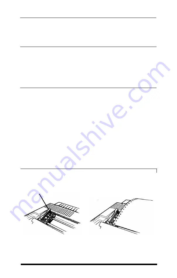
6. Open the covers on the sprocket units as shown in Figure 2-3, then
move the right sprocket unit to its approximate position, using your
paper as a guide. Put the ridged paper support midway between the
two sprocket units.
7. Make sure that the first sheet of paper has a clean edge and that the
perforated edges are still attached.
8. Fit the first four holes in the left side of the paper over the pins of
the left sprocket unit, as shown in Figure 2-4; then close the cover.
9. Now move the right sprocket unit so that you can fit the holes in the
paper over the pins and close the cover.
Figure 2-3.
Figure 2-4.
Opening the sprocket units
Position@ the paper
Sprocket unit
cover
2 - 4
Choosing and Loading Paper
Summary of Contents for EX-1000
Page 1: ......
Page 11: ......
Page 29: ...1 18 Setting Up the Printer ...
Page 38: ......
Page 46: ...3 8 Using the EX with Application Programs ...
Page 51: ......
Page 57: ...5 6 EX Printer Features ...
Page 76: ......
Page 81: ...Command Summary A 5 ...
Page 82: ...A 6 Command Summary ...
Page 121: ......
Page 123: ...Table B 1 Epson mode characters B 2 Character Tables ...
Page 124: ...Table B 1 continued Character Tables B 3 ...
Page 125: ...Table B 1 continued B 4 Character Tables ...
Page 126: ...Table B 1 continued Character Tables B 5 ...
Page 127: ...Table B 1 continued B 6 Character Tables ...
Page 128: ...Table B 1 continued Character Tables B 7 ...
Page 129: ...Table B 1 continued B 8 Character Tables ...
Page 133: ...Table B 4 IBM printer emulation mode characters B 12 Character Tables ...
Page 134: ...Table B 4 continued Character Tables B 13 ...
Page 135: ...Table B 4 continued B 14 Character Tables ...
Page 137: ...Table B 4 continued B 16 Character Tables ...
Page 139: ...Table B 4 continued B 18 Character Tables ...
Page 151: ...D 8 Problem Solving and Maintenance ...
Page 157: ...E 6 Defaults and DIP Switches ...
Page 172: ......
Page 173: ...G 8 Technical Specifications ...
Page 183: ...IN 4 Index ...
Page 184: ...Quick Reference ...
Page 186: ......
Page 187: ......
Page 188: ......
Page 189: ......
Page 190: ......


