


EPSON Stylus CX4100/CX4200/CX4700/CX4800/DX4200/DX4800/DX4850
Revision A
OPERATING PRINCIPLES
Electrical Circuit Operating Principles
84
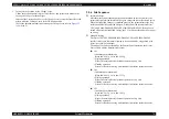
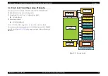
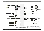
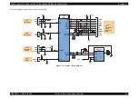
2.4.2.4 Combination Circuit
This printer differs from previous models by using a combination IC that integrates the
reset circuit, EEPROM and RTC.
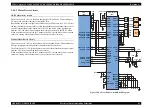
Reset Circuit
RTC IC (IC4) on the Main Board monitors the three voltage: +3.3V for the logic line,
+5V for the logic line and +42V for the drive line. Reset Circuit outputs the reset signal
to CPU (IC8) in the following case.
+3.3V line reset circuit
The 3.3V line is monitored at the VDD port of IC4, and if an abnormal voltage is
detected, a reset signal for the CPU is output from the FRST port ofIC4.
+5V line reset circuit
The 5V line is monitored at the VDD2 port of IC4, and if an abnormal voltage is
detected, a reset signal for the CPU is output from the RST port of IIC4.
+42V line reset circuit
The 42V line is monitored at the VEX port of IC4, and if an abnormal voltage is
detected, a reset signal for the CPU is output from the EXO port of IC4.
EEPROM Control Circuit
When the printer power is turned off, the following information is stored in EEPROM
(IC4) which is nonvolatile memory. And, when the printer power is on, CPU (IC8)
reads the information from EEPROM.
Information stored in EEPROM is listed below.
Various ink counter (I/C consumption counter, Waste Ink Pad counter, etc.)
Mechanical setting value (Head ID, Bi-D Adjustment, USB ID, etc.)
EEPROM is connected to CPU with 4 lines and each line has the following function.
CE:
Chip selection signal
CLK:
Data synchronism clock pulse
DI:
Data writing line (serial data) at power off.
DO:
Data reading line (serial data) at power on.
RTC Circuit
By adoption of the large-capacity capacitor (C9) for timer, the Power-off timer can be
backed up for about one week after power-off.
Figure 2-21. RTC Circuit Block Diagram
+42V
VDD
VIS
VDD2
VEX
VSS
CE
CLK
DI
DO
EXO
FRST
RST
+5V
+3.3V
+3.3V
+3.3V
TCE
TCLK
TDO
TIMDI
MNII
MRES
/RESET
F2
E4
E3
D3
E2
D1
E1
RTC
(IC4)
CPU
(IC8)
C11
14
12
8
10
7
5
4
3
2
9
13
11
Summary of Contents for CX4200 - Stylus Color Inkjet
Page 9: ...C H A P T E R 1 PRODUCTDESCRIPTION ...
Page 60: ...C H A P T E R 2 OPERATINGPRINCIPLES ...
Page 87: ...C H A P T E R 3 TROUBLESHOOTING ...
Page 121: ...C H A P T E R 4 DISASSEMBLY ASSEMBLY ...
Page 171: ...C H A P T E R 5 ADJUSTMENT ...
Page 187: ...C H A P T E R 6 MAINTENANCE ...
Page 194: ...C H A P T E R 7 APPENDIX ...
Page 221: ...Model PX A650 Stylus CX4700 CX4800 DX4800 DX4850 Board C571 PNL Rev D Sheet 1 1 ...
Page 222: ...Model Stylus CX4100 CX4200 DX4200 Board C577 PNL Rev A Sheet 1 1 ...


