


EPSON Stylus CX4100/CX4200/CX4700/CX4800/DX4200/DX4800/DX4850
Revision A
DISASSEMBLY/ASSEMBLY
Printer Section
157
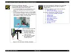
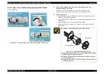
4.4.22 EJ Frame Unit
External view (1)
Figure 4-40. Removing EJ Frame Unit
Part/Unit that should be removed before removing EJ Frame Unit
Document Cover / Paper Support Assy. / Scanner Unit / Panel Unit /
Housing Upper / Print Head / Printer Mechanism / Main Board Unit /
CR Guide Frame / CR Motor / Carriage Unit / Front Frame
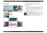
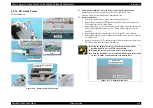
Removal procedure
1.
Peel off the acetate tape (x1) that secures the PG Sensor Connector Cable.
2.
Remove the Paper Eject Grounding Spring from the left side of the EJ Frame
Unit.
3.
Release the guide pin (x1, ) of Bush 5 on the left side of the EJ Frame Unit,
and rotate the Bush 5 downward by 90
°
.
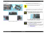
4.
Release the guide pin (x1, )of Bush 5 on the right side of the EJ Frame Unit,
and rotate the Bush 5 upward (or downward) by 90
°
.
5.
Release the tabs (x3, ) that secure the EJ Frame Unit while lifting the near
side of the EJ Frame Unit upward.
Right Side
Bush 5
Bush 5
Acetate
Tape
Left Side
Paper Eject
Grounding Spring
Tabs
EJ Frame Unit
C A U T I O N
Do not hold the EJ Frame Unit while handling the Printer
Mechanism in your repair.
Do not touch the rubber portion of the Eject Roller.
Summary of Contents for CX4200 - Stylus Color Inkjet
Page 9: ...C H A P T E R 1 PRODUCTDESCRIPTION ...
Page 60: ...C H A P T E R 2 OPERATINGPRINCIPLES ...
Page 87: ...C H A P T E R 3 TROUBLESHOOTING ...
Page 121: ...C H A P T E R 4 DISASSEMBLY ASSEMBLY ...
Page 171: ...C H A P T E R 5 ADJUSTMENT ...
Page 187: ...C H A P T E R 6 MAINTENANCE ...
Page 194: ...C H A P T E R 7 APPENDIX ...
Page 221: ...Model PX A650 Stylus CX4700 CX4800 DX4800 DX4850 Board C571 PNL Rev D Sheet 1 1 ...
Page 222: ...Model Stylus CX4100 CX4200 DX4200 Board C577 PNL Rev A Sheet 1 1 ...


