


EPSON Stylus CX4100/CX4200/CX4700/CX4800/DX4200/DX4800/DX4850
Revision A
DISASSEMBLY/ASSEMBLY
Printer Section
129
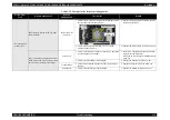
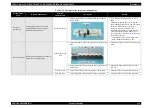
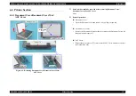
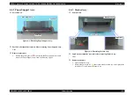
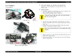
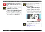
4.4.4 Scanner Unit
External view (1)
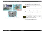
Figure 4-5. Removing Scanner Unit
Part/Unit that should be removed before removing Scanner Unit
Document Cover
Removal procedure
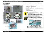
1.
Release the tabs (x2,
) that secure the USB Cover with a precision
screwdriver (-), and remove the USB Cover.
2.
Remove the screw (x1, ) that secure the FFC Shield Plate, and remove the
FFC Shield Plate.
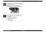
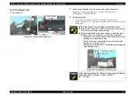
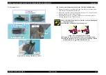
3.
Disconnect the following Connector Cables and FFC from the connectors on
the Main Board.
• CN10: Scanner Motor Connector Cable
• CN11: Scanner Carriage FFC
• CN13: Scanner HP Sensor Connector Cable
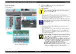
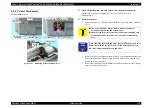
4.
Remove the screws (x2,
) that secure the Scanner Unit.
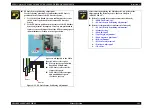
5.
Open the Scanner Unit, and remove it by pulling out upward.
USB Cover
2
1
CN10
CN13
CN11
Main Board
FFC Shield Plate
C.B.S. 3x6 F/Zn
(6±1kgfcm)
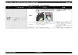
Rib
FFC
Main Board Unit
Double-sided Tape
Step 5-1
Step 5-2
C.B.P. 3x10 F/Zn
(6±1kgfcm)
Guide Pin
C.B.P. 3x10 F/Zn
(6±1kgfcm)
Scanner Unit
Housing, Upper
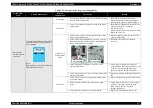
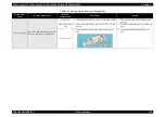
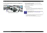
C A U T I O N
Do not damage the Scanner Carriage FFC when removing/
installing the screw (
).
The Scanner Carriage FFC is fastened with the double-sided
tape, so be careful not to damage the FFC when removing it.
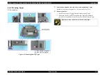
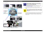
Do not pinch the FFC or any Connector Cables between the
Scanner Unit and the Housing, Upper.
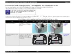
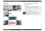
Route the Scanner HP Sensor Connector Cable around the
channel of Hinge L.
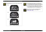
Figure 4-6. Routing Connector Cable
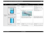
Align the guide pin (x1,
) of the Scanner Unit and the
positioning hole (x1) of the Housing Upper.
Insert the rib (x1) of the FFC Shield Plate into the notch (x1,
).
1 2
Scanner HP Sensor
Connector Cable
Hinge L
Groove
Summary of Contents for CX4200 - Stylus Color Inkjet
Page 9: ...C H A P T E R 1 PRODUCTDESCRIPTION ...
Page 60: ...C H A P T E R 2 OPERATINGPRINCIPLES ...
Page 87: ...C H A P T E R 3 TROUBLESHOOTING ...
Page 121: ...C H A P T E R 4 DISASSEMBLY ASSEMBLY ...
Page 171: ...C H A P T E R 5 ADJUSTMENT ...
Page 187: ...C H A P T E R 6 MAINTENANCE ...
Page 194: ...C H A P T E R 7 APPENDIX ...
Page 221: ...Model PX A650 Stylus CX4700 CX4800 DX4800 DX4850 Board C571 PNL Rev D Sheet 1 1 ...
Page 222: ...Model Stylus CX4100 CX4200 DX4200 Board C577 PNL Rev A Sheet 1 1 ...


