


EPSON Stylus CX4100/CX4200/CX4700/CX4800/DX4200/DX4800/DX4850
Revision A
OPERATING PRINCIPLES
Electrical Circuit Operating Principles
79
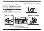
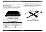
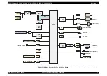
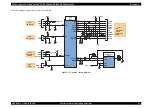
2.4.1 C610 PSB/PSE Board
In the PSB/PSE Board of Stylus CX4100/CX4200/CX4700/CX4800/DX4200/
DX4800/DX4850, the simulated oscillating stimulation flyback converter circuit
method is used, and it su42VDC to the drive line. The application of the output
voltage is described below.
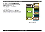
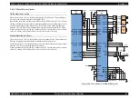
AC voltage input from AC inlet first goes through filter circuit that removes high
frequency components and is then converted to DC voltage via the rectifier circuit and
the smoothing circuit. DC voltage is then lead to the switching circuit and FET Q1
preforms the switching operation. By the switching operation of the primary circuit,
+42VDC is generated and stabilized at the secondary circuit.
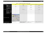
Table 2-7. Application Of The DC Voltages
Voltage
Application
+42VDC
• Motors (CR Motor, PF Motor, Scanner Motor)
• Print Head common voltage
• Print Head nozzle selector 42V drive voltage
Summary of Contents for CX4200 - Stylus Color Inkjet
Page 9: ...C H A P T E R 1 PRODUCTDESCRIPTION ...
Page 60: ...C H A P T E R 2 OPERATINGPRINCIPLES ...
Page 87: ...C H A P T E R 3 TROUBLESHOOTING ...
Page 121: ...C H A P T E R 4 DISASSEMBLY ASSEMBLY ...
Page 171: ...C H A P T E R 5 ADJUSTMENT ...
Page 187: ...C H A P T E R 6 MAINTENANCE ...
Page 194: ...C H A P T E R 7 APPENDIX ...
Page 221: ...Model PX A650 Stylus CX4700 CX4800 DX4800 DX4850 Board C571 PNL Rev D Sheet 1 1 ...
Page 222: ...Model Stylus CX4100 CX4200 DX4200 Board C577 PNL Rev A Sheet 1 1 ...


