


EPSON Stylus CX4100/CX4200/CX4700/CX4800/DX4200/DX4800/DX4850
Revision A
OPERATING PRINCIPLES
Electrical Circuit Operating Principles
82
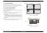
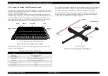
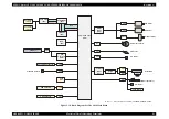
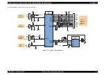
2.4.2.2 Print Head Driver Circuit
The Print Head driver circuit consists of the following two components:
Head common driver circuit (Common driver IC7 & Wave amplifier
transistor Q3, Q4)
Nozzle selector IC on the Print Head driver
The common driver (IC7) generates a basic drive waveform according to the output
signals from CPU (IC8). The basic drive waveform is amplified by the transistors Q3
and Q4 (the amplified one is called drive waveform.) and then transferred to the nozzle
selector IC on the Print Head driver board. Print data is converted to serial data by the
CPU and then sent to the nozzle selector IC on the Print Head driver board. Based on
the serial data, the nozzle selector IC determines the nozzles to be actuated. The
selected nozzles are driven by the drive waveforms amplified by the transistor Q3 and
Q4. Refer to
for the Print Head driver circuit block diagram.
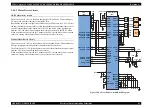
Head common driver circuit
The basic drive waveform is generated in the common driver (IC7) based on the
following 13 signal lines output from the CPU (IC8); DATA0-DATA9, LAT,
RESET, and PSCNT.
By the DATA signal output from the CPU, the original data for the basic drive
waveform is written in the memory in the common driver (IC7). The addresses for
the written data are determined by DATA0-DATA9 signals. Then, the necessary
data is selected from the address and appropriate basic drive waveform is
generated. Generated basic drive waveform is transferred to nozzle selector IC on
the Print Head driver board through the transistor Q3 and Q4 and applied to the
nozzle PZT specified by nozzle selector IC.
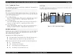
Nozzle selector circuit
Printing data is allocated to the four rows (the number of the head nozzle rows)
and converted into serial data by the CPU (IC8). Then the converted data is
transferred to the nozzle selector IC through the four signals lines (HS01 to HS04).
Data transmission from the CPU to the nozzle selector synchronizes with the LAT
signal and SCK clock signal. Based on the transmitted data, appropriate nozzle is
selected and the PZTs of the selected nozzle are driven by the drive waveform
output from the head common driver.
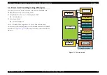
Figure 2-19. Print Head Driver Circuit
CPU
(IC8)
Common
Driver
(IC7)
Nozzle
Selector IC
+42V
Head
Drive
Pulse
CN6
CN5
HDAC_D0
HDAC_D1
HDAC_D2
HDAC_D3
HDAC_D4
HDAC_D5
HDAC_D6
HDAC_D7
HDAC_D8
HDAC_D9
HDAC_CLK
HDAC_RST
PC1
COM
COM
CH
SCK
SI3_Ma
SI4_Cy
DATA0
DATA1
DATA2
DATA3
DATA4
DATA5
DATA6
DATA7
DATA8
DATA9
LAT
RST
PSAVE
4
3
2
1
30
29
28
27
26
25
5
6
23
F1
+3.3V
22
Q3
5
2
4
9
11
11
13
8
6
4
2
1
7
13
Q4
F2
20
18
16
C2
B1
C1
D2
B3
A2
B2
A1
C9
HCH
HSOCLK
HS03
HS04
HLAT
NCHG
HS01
HS02
AIN1
C10
C11
C12
D13
C13
A12
B12
A11
B11
D10
B13
A13
A10
J3
NPNB
FB
PNPB
VHV
COM
COM
LAT
NCHG
SI1_Bk
SI2_Ye
XHOT/TMM
VCC45
Summary of Contents for CX4200 - Stylus Color Inkjet
Page 9: ...C H A P T E R 1 PRODUCTDESCRIPTION ...
Page 60: ...C H A P T E R 2 OPERATINGPRINCIPLES ...
Page 87: ...C H A P T E R 3 TROUBLESHOOTING ...
Page 121: ...C H A P T E R 4 DISASSEMBLY ASSEMBLY ...
Page 171: ...C H A P T E R 5 ADJUSTMENT ...
Page 187: ...C H A P T E R 6 MAINTENANCE ...
Page 194: ...C H A P T E R 7 APPENDIX ...
Page 221: ...Model PX A650 Stylus CX4700 CX4800 DX4800 DX4850 Board C571 PNL Rev D Sheet 1 1 ...
Page 222: ...Model Stylus CX4100 CX4200 DX4200 Board C577 PNL Rev A Sheet 1 1 ...


