

Owner's Manual for EPILOG Legend Model 6000
December, 2000
Section 14 – Servicing the Legend
77
LASER MODULE
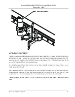
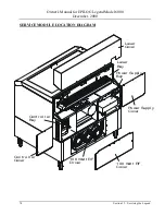
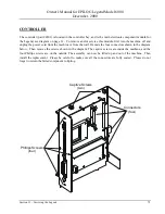
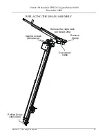
The laser module for the Legend (part #LM3-25/3-30/3-35/4-60/4-80/4-100) is located in the laser bay, see
diagram on page 61. To remove and/or service this module, turn the machine off and unplug the power cord
from the machine. Remove the laser cover. The cover is secured with four or five Phillips head screws along
the lower edge of the cover. Once the cover is free, there is a connector under the cover that you will need to
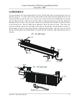
disconnect before you can set the cover aside. The laser on your machine will resemble one of the two shown
in the drawing below. There are differences in appearance that do not effect servicing. First remove the
electrical connectors, then the three allen head screws shown in the drawings. The RF connection on the 50 -
100 watt lasers can only be removed once the laser is lifted out of the machine. Once the screws are free, lift
the laser off the hangers and it should pull free (except for the RF connection, which should be unscrewed at
this time).
25 - 40 watt laser
CONNECTOR
CONNECTOR
SCREW
SCREW
SCREW
CONNECTOR
50 - 100 watt laser
SCREW
SCREW
SCREW
RF Connection
(located on rear or bottom of laser)
CONNECTOR


