background image

24

GB

Important notes

• 

Unprofessional installation may cau-

se a fi re hazard! Please read these instal-
lation instructions carefully. In particular, 
please observe the dimensions stated and 
the following notes.

• 

This device can be used by children aged 
8 upwards and by persons with physical, 
sensory,  or  mental  disabilities,  or  who 
have  inadequate  experience  and  know-
ledge if they are supervised or if they have 
received  adequate  instruction  in  how  to 
use the device safely and understand the 
associated  risks.  Children  may  not  play 
with  this  device.  Children  may  not  clean 
or carry out any user maintenance if un-
supervised. 

• 

Children  should  be  supervised  to  make 
sure that they will not play with the unit.

• 

 Only specialists may install and con-

nect  the  sauna  heater,  control  unit  and 
other  electrical  equipment  with  a  fi xed 
mains  connection. The  necessary  protec-
tive measures according to VDE 0100 of § 
49  DA/6  and VDE  0100  part  703/2006-2 
must be observed.

• 

Sauna  heater  and  controller  may  only  be 
used in sauna cabins made of suitable, low-
resin, untreated materials (e.g. spruce).

• 

Only a sauna heater with the appropriate 
power output may be installed in the sau-
na cabin.

• 

Please  provide  air  intake  and  vent  ope-
nings in each sauna cabin. The air intakes 
must  always  be  positioned  behind  the 
sauna  heater,  approx.  5  to  10  cm  above 
the fl oor. The minimum dimensions of the 
air intake and vent openings are stated in 
the table.

• 

The duct vents are always to be positioned 
off set  diagonally  to  the  sauna  heater  in 
the lower area of the rear sauna wall. The 
air intake and vents may not be covered. 
Please observe the sauna cabin supplier's 
instructions.

• 

Only  the  control  units  specifi ed  herein 
must  be  used  for  the  operation  of  the 
sauna  heater.  This  control  unit  must  be 
positioned at an appropriate point on the 
cabin  outer  wall;  the  associated  sensor 
must be positioned inside the sauna cabin 
according  to  the  installation  instructions 
included with the control unit.

• 


Caution: 

Covering the heater or an 

incorrectly fi lled stone container represent 
a fi re hazard.

• 

 Every time before the sauna is used, 

ensure that no objects have been left lying 
on the sauna heater.

• 


Caution:

  The  high  sauna  heater 

temperatures generated during operation 
can cause burns.

• 

The  sauna  heater  is  not  intended  for  in-

Summary of Contents for Herkules S60

Page 1: ...1 D MADE IN GERMANY IP x4 Druck Nr 29343633 28 14 Herkules S60 S60 vapor D Montage und Gebrauchsanweisung Assembly and operating instruction GB RU...

Page 2: ...2 Deutsch 3 English 20 37...

Page 3: ...rumfang 9 Mindestabst nde 9 Sicherheitstemperaturbegrenzer 10 Festwasseranschluss 11 Nur bei Vapor Ger ten 11 Montage des Abdeckschutzes am Saunaofen 13 Finnischer Saunabetrieb 14 Klimabetrieb nur bei...

Page 4: ...eliefert hat Beachten Sie dass Sie ein optimales Saunaklima nur dann erreichen wenn die Kabine mit ihrer Zuluft und Abluft das Saunaheizger t und das Steuerger t aufeinander abgestimmt sind Beachten S...

Page 5: ...100 v 49 DA 6 und VDE 0100 Teil 703 2006 2zubeachten Saunaheiz und Steuerger t d rfen nur in Saunakabinen aus geeignetem harz armen und unbehandeltem Material z B Nordische Fichte verwendet werden In...

Page 6: ...stens 170 C geeignet Werden als Anschlussleitung einadrige Leitungen verwendet m s sen diese durch ein biegsames mit dem Schutzleiter verbundenes Metallrohr ge sch tzt werden Den Mindestquerschnitt de...

Page 7: ...r ber dem Bereich der Steine aufgiessen Bei finnischer Badeform nie Kr uter oder hnlichesineine fallsvorhanden Auf nahmeschale legen Brandgefahr Achten Sie bei der Kabinenausf h rung darauf dass ber h...

Page 8: ...erbindung Netz Steuerger t Verbindung Netz LSG Verbindung Steuerger t Ofen Verbindung LSG Ofen Verbindung Steuerger t LSG 9 0 kW 3N AC 50 Hz 400 V 3 x 16 5 x 2 5 5 x 1 5 12 0 kW 3 x 16 5 x 2 5 5 x 1 5...

Page 9: ...unit Bo tier de commande Saunaheizger t Sauna heater Po le de sauna 5 5 Netz Mains R seau 3 4 optional 9 kW Ofen leistung nach DIN Verdampfer leistung Einbau ma e in cm H B T f r Kabinen volumen Minde...

Page 10: ...erialien zum Ofen muss mindestens 4 cm betragen Die H he des Ofenschutz gitters muss etwa der vorderen Ofenh he Kabinenwand Ofenschutzgitter Abb 1 Anschlussleitung nach Schaltplan anschlie en Ein Scha...

Page 11: ...ale abnehmen Abb 2 Sicherheits temperaturbe grenzer STB Abb 5 Abb 2 Zum Entfernen der Abdeckung l sen Sie bitte ebenfalls die beiden r ckseitig befes tigten Schrauben Die Abdeckung l sst sich jetzt na...

Page 12: ...estwasseranschlusses einen Fitting Winkel B2 und eine Schlaucht lle C Wichtige Hinweise Die Vorschriften der EN 1717 bzw der DIN 1988 Teil 4 sind zu beachten Es sind geeignete Ma nahmen zu treffen die...

Page 13: ...en Beh lter Achten Sie darauf dass der Schwimmk rper eine senkrechte Bewe gung ausf hrt und nicht an der Beh lter wand anschl gt Am Abgang des Schwimmerventils ist ein 3 4 Gewinde Von hier k nnen Sie...

Page 14: ...s am Saunaofen alle Blechschrauben f r Aufh ngung Ofenschutz alle metrischen Schrauben f r Aufh ngung Abschaltwippe alle Ma angaben in mm Ansicht A 2 Blechschrauben 2 Blechschrauben Befestigungsklamme...

Page 15: ...r Achtung Aufgusswasser immer nur ber dem Bereich der Steine auf giessen Bei dieser Badeform nie Kr uter oder hnliches in die Verdampfer schale legen Brandgefahr Klimabetrieb nur bei Herkules vapor Ac...

Page 16: ...rsten Gebrauch sp len Sie den Verdampfer bitte durch und bef llen Sie diesen anschlie en d mit frischem Wasser Die Regelung des Verdampfers erfolgt ber das Steuerger t Entweder erhalten Sie einen Feuc...

Page 17: ...eben Sie hierzu Entkalker f r Haushaltsger te der auch f r Aluminiumgef e tauglich ist nach Angaben des Herstellers dem Wasser im Verdampfer bei Das Wasser Entkalkergemisch ca 10 Minuten zum Kochen br...

Page 18: ...en Materialen gefertigt Damit Sie lange Freude mit Ihrem Saunaheizger t haben sollten Sie das Ger t warten und pflegen Dabei m ssen Sie darauf achten dass die im Ansaugbereich befindlichen ffnungen un...

Page 19: ...FI Schalter ab gesichert werden Nach dem heutigen Stand der Technik ist es nicht sinnvoll dampfdichte Rohrheizk rper f r Sauna fen einzusetzen Es kann vorkommen dass die Magnesiumoxidf llung der Heiz...

Page 20: ...beschreibung anzugeben Diese Garantie umfasst die Verg tung von de fekten Ger teteilen mit Ausnahme normaler Verschlei erscheinungen Bei Beanstandungen ist das Ger t in der Original verpackung oder ei...

Page 21: ...er H ndler sollte stets Ihr erster Ansprechpart ner sein denn dort ist man am besten mit dem hauseigenen Produkt vertraut und kennt eventuelle Problemf lle Bei Funktionsproblemen mit einem Artikel pr...

Page 22: ...nts 26 Minimum distances 26 Temperature safety device 27 Fixed water connection 28 Only on vapor devices 28 Assembly of the protective cover on the sauna heater 30 Using a Finnish sauna 31 Air conditi...

Page 23: ...pped the goods Please note that you will only be able to achieve anoptimumsaunaclimateifthecabinwithitsair intake and ventilation the sauna heater and the control unit are aligned to each other Please...

Page 24: ...resin untreatedmaterials e g spruce Only a sauna heater with the appropriate power output may be installed in the sau na cabin Please provide air intake and vent ope nings in each sauna cabin The air...

Page 25: ...that the vertical clearance be tween the sauna heater upper edge and the sauna ceiling is maintained Please see also the dimensions diagram for the clearance between the lower edge of the sauna heater...

Page 26: ...bin Most sauna cabins have empty ducts fitted into the wall element with the air intake If no empty ducts are available in your cabin drill a sufficiently sized hole in the cabin wall directly next to...

Page 27: ...IN Installation dimensions H W D cm For cabin size Minimum dimensions of air intake and exhaust vents Weight without stones without package Stone lling Power switch gear LSG needed For operation with...

Page 28: ...es without package Stone lling Power switch gear LSG needed For operation with control units 9 0 kW 2 0 kW 8 l 85 53 53 9 14 m 35 x 6 cm 53 kg EMOTEC H EmoTouch II 12 0 kW 14 18 m 35 x 7 cm 60 kg EMOT...

Page 29: ...mable materials near the heater must be at least 4 cm The heater grid must be more or less the same Cabin wall safety grid Fig 1 Complete the connections as shown in the circuit plan The circuit plan...

Page 30: ...able to remove the lower frame together with the evaporator dish Fig 2 Te m p e r a t u r e safety device STB Fig 5 Fig 2 Remove the cover by loosening the two screws on the back Next remove the lid b...

Page 31: ...iece of silicone hose E provid ed between the two hose nozzles C and secure it using the hose clamps provided Important notes Observe the regulations laid down in EN 1717 or the DIN 1988 Part 4 Take s...

Page 32: ...tact the tank wall There is a 3 4 thread on the oat valve output From here you can now connect your supply line individually to the xed water connection Please observe A shut off valve must be install...

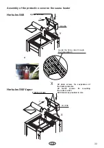
Page 33: ...on the sauna heater All plate screws for suspension of the heater protector All metric screws for mounting the rocker switch All dimensions provided in mm A 2 plate screws 2 plate screws Guide the fi...

Page 34: ...risk of re Danger Always pour the water con taining an infusion over the stones and never anywhere else When you are using the Finnish bath never put herbs or anything similar into the evaporator dish...

Page 35: ...h hazard cannot be removed It is advised not to use those ad ditives apart from the recommended ones by the manufacturer of the oven If additives are put in the water this generally leads to a foaming...

Page 36: ...stones will re heat suffici ently again Never add more essences or volatile oils than advised on the packaging Never use alcohol or undiluted concentrates Cau tion Fire hazard All sauna heating units...

Page 37: ...rical units will be protected by this ELCB Under current manufacturing technology it is not reasonable to use heating elements for sau na heaters which do not collect moisture from the surrounding air...

Page 38: ...el name with detailed description of the fault This guarantee covers defective parts and la bour but not the defects caused by wear and tear In case of complaint please return the equip ment in its or...

Page 39: ...u the individual case and try for immediate and customer friendly solu tion For economic returns within Germany you will get an RMA number from the manufacturer All returns have to be in the original...

Page 40: ...40 RU 38 38 39 40 Herkules S60 41 T 41 Herkules S60 vapor 42 T 42 43 43 43 44 Vapor 45 47 48 Herkules vapor 48 48 48 49 50 50 51 51 RMA 52...

Page 41: ...41 RU DIN EN ISO 9001 2008 110 C 30 40 C 110 C 20 25 85 C 80 90 C 76 C...

Page 42: ...42 RU 8 VDE 0100 49 DA 6 VDE 0100 703 2006 2 5 10...

Page 43: ...43 RU DIN EN VDE 0100 T 703 40 170 C...

Page 44: ...44 RU S Guard...

Page 45: ...II 12 0 14 18 m 35 x 7 cm EMOTEC L09 15 0 18 25 m 35 x 9 cm LSG 5 5 5 4 5 4 Saunasteuerger t Control unit Bo tier de commande Saunaheizger t Sauna heater Po le de sauna Leistungsschaltger t Power ext...

Page 46: ...x 7 cm EMOTEC L09 15 0 18 25 m 35 x 9 cm 4 Saunasteuerger t Control unit Bo tier de commande Saunaheizger t Sauna heater Po le de sauna 5 5 Netz Mains R seau 3 4 optional 9 4 Saunasteuerger t Control...

Page 47: ...47 RU 4 cm 53 cm 4 cm 4 cm 53 cm 1 90 105 4 1 1 1 4 1 Herkules S60 vapor Herkules S60 4 cm 51 cm 4 cm 4 cm 53 cm 1a 4...

Page 48: ...48 RU STB S 2 STB 5 2 3 3 4 STB 4 1 2 3 400 VDE 2...

Page 49: ...49 RU 94 4779 S60 vapor 1 2 1 2 1 2 1 B1 C B2 C EN 1717 DIN 1988 4 Vapor A 1 2 20 B 1 2 ii 90 C 1 2 v 13 MS D 17 3 E 1 1 2 3 4 1a 3 4 1 2 A B1 B2 E D C 1 150 180 65 1 2 1c 1b 1d...

Page 50: ...50 RU E C 2 4 2x9 5 3 4 6...

Page 51: ...51 RU 1 2 X 94 4708 X X 1 2 94 4708 A 2 2 Herkules S60 Herkules S60 Vapor...

Page 52: ...52 RU I Herkules vapor 1 2 max...

Page 53: ...53 RU 4 5 5 1 0 8 4 II Ill 10...

Page 54: ...54 RU 100 10...

Page 55: ...55 RU 121471 928 7 495 564 8772 564 8773 995 9744 775 9965 7 495 564 8773 info eos werke ru www eos werke ru EOS Saunatechnik GmbH Schneiderstriesch 1 35759 Driedorf Deutschland 3 2...

Page 56: ...56 RU RMA RMA RMA 3 1 2 2 RMA...

Reviews: