background image

Page 71

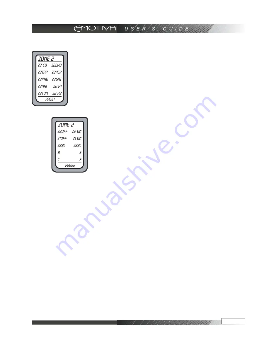
PAGE 1
This allows you to select the inputs to play in Zone 2. Z2MAI (main) allows
Zone 2 to play whatever is playing in the Main Zone.

Press PAGE to show the next page:
PAGE 2 / This has discrete codes which are useful if you want to program
the remote control with Macros.
Z2 OFF, Z2 ON Zone 2 on or off.
Z1 Off, Z1 ON

Main Zone on or off.
Z2 BL
Use these two buttons to adjust the left-right balance of Zone 2.
B, C, E, F
These are extra buttons you can Learn over and re-Label with your
favorite Zone 2 commands.
Press MAIN to return to PAGE 1, and press it again to return to the
MAIN menu.
Note: Zone 2 can also be turned on and adjusted without using the
remote. Press the Zone 2 button on the DMC-1 front panel, fol-
lowed by Power, to turn it on (or off), or adjust the input source or
volume.

Note: Zone 2 operations will work even if the Main Zone is off.

Summary of Contents for DMC-1

Page 1: ...professional AV Processor USER S GUIDE...

Page 2: ......

Page 3: ...rocessor Display 14 Z II Zone 2 15 Input Select Buttons 15 MODE UP DOWN Mode Buttons 15 AM FM Tuner Controls 15 Tone Controls 15 Signal Processing Indicator Lights 15 Additional Front Panel Features 1...

Page 4: ...DVD Video Player Analog Audio and Composite Video 26 Connecting a DVD Video Player Digital Audio and Component Video 27 Connecting to the TV or Projector using Component Video 28 Connecting a VCR Anal...

Page 5: ...SD Functions 50 Video Connections 50 OSD Activation 50 Quick Access to Information 50 OSD Menus 51 How to Navigate the OSD Menus 51 TRIM Menu 51 MODES Menu 52 Dynamic Range 52 Pro Logic IIx Sub Menu 5...

Page 6: ...rround Back Speakers 76 Subwoofer Location 76 Remote Control Codes 78 Audio Components 78 Auxiliary Devices 78 Cable Boxes 79 CD Players 79 DVD Players 80 Laserdisc Players 80 Satellite DSS Receivers...

Page 7: ...s of Noise 89 Favorite Settings Log 90 Tone Settings 90 Main Zone Settings 90 Zone 2 Settings 90 Mode Settings 90 Control Settings 91 Video Settings 91 Input Settings and Remote Codes 92 SPEAKER Setti...

Page 8: ...nt rack that may impede the flow of air through ventilation openings If installed in a closed equipment rack for custom installations be sure to add forced air ventilation so that it has adequate air...

Page 9: ...noise emissions from digital apparatus as set out in the radio interference regulations of the Canadian Department of Communications ATTENTION Le present appareil numerique n emet pas de bruits radio...

Page 10: ...enna Grounding Outside the House If an outside antenna is connected to the receiver be sure the antenna system is grounded so as to provide some protection against voltage surges and built up static c...

Page 11: ...eo sources without requiring an engineering degree to operate the component What s more the Emotiva DMC 1 does it all with exceptionally refined cosmetics and a sound quality that will satisfy even th...

Page 12: ...e your Emotiva DMC 1 ever needs to be moved or shipped back to the factory for service Make sure that you keep your sales receipt It is the only way for Emotiva to establish the duration of your Limit...

Page 13: ...ors for DVD Audio format Three component video inputs and two component video outputs Automatic video format transcoder up converts Composite and S Video source to Compo nent Video Six coaxial and fou...

Page 14: ...ow such as 80 dB and increase it slowly The dB display becomes less negative as the volume increases The DMC 1 volume control is velocity sensi tive If turned slowly the volume will change in small in...

Page 15: ...he unit returns to its normal display after a few moments of inactivity and any level changes are retained The BASS and TREBLE levels can also be adjusted using the OSD TONE Menu and the remote contro...

Page 16: ...light is on when Zone 2 is turned on ZONE TWO ADJUST This light is on when Zone 2 is being adjusted SIDE AXIS This light is on when the side axis outputs are enabled PANEL DIM Button The front panel...

Page 17: ...for MON2 the output is always active the same as the Main output Note Analog audio signals are present at these L and R outputs even if a digital input has been selected The output is a 2 channel dow...

Page 18: ...al control device intended to be installed in a remote location XLR Audio Outputs These line level balanced XLR outputs connect to the XLR inputs of your amplifi ers and powered subwoofer The outputs...

Page 19: ...can be fitted for improved reception AM Antenna These connections are for the included AM loop antenna Audio Outputs These audio outputs connect to the ana log record inputs of your tape decks such as...

Page 20: ...and CD inputs have two options optical or coaxial The DAT and VID2 inputs are coaxial only Whenever one of these inputs is selected from the front panel or remote the DMC 1 will automatically select...

Page 21: ...ow the DMC 1 to share a wall socket with other video source units but power amplifiers and a video display big screen TV or video projector should each be provided a SEPARATE electrical connec tions o...

Page 22: ...ws the direction of signal flow It is usual for the right channel RCA patch cord plugs to be red and the left channel connec tions to be white grey or black depending on the cable brand RCA connectors...

Page 23: ...5 ohm coax or twisted pair cables to carry the separate Y luminance and C chrominance signals Picture Quality Better The S video cable will offer marked improvement over a composite cable What is Comp...

Page 24: ...s for the Tuner Tape or Phono sources so the video output will remain on the last selected video source until another input with video source capabilities is selected Video Output to the Main Screen a...

Page 25: ...DC loads of 2 A maximum Typically this will mean low voltage control of structured lighting systems automated window coverings or other low voltage devices Never switch anything that plugs directly in...

Page 26: ...ks and video output is taken from the Composite Video output the Yellow RCA jack When you select DVD on the DMC 1 the audio output from the DVD player will play through the audio system and video will...

Page 27: ...deo outputs the Red Blue Green trio When you select DVD on the DMC 1 the audio output from the DVD player will play through the audio system and video will appear on the TV or projector you must first...

Page 28: ...the DMC 1 This configuration will give the best picture quality especially if the video source component output begins as a native Component Video output Remember that with the video transcoding feat...

Page 29: ...deo output is taken from the Com posite Video output the Yellow RCA jack If you plan to use the VCR for recording you also must connect the DMC 1 s VCR outputs into the VCR inputs This configuration a...

Page 30: ...CD on the DMC 1 the audio output from the CD player will play through the audio system While this method of connection is normal if the CD player is equipped with an optical digital output you may ch...

Page 31: ...e inputs and outputs on the DMC 1 can be connected to TAPE or DAT If you have both types connected the DMC 1 will switch automati cally on to whichever source is playing You can t have both playing at...

Page 32: ...digital signal processing functions of the DMC 1 including the tone controls surround processing and bass management features This provides the purest signal quality for high resolution DVD A or SACD...

Page 33: ...ith two wires that connect into the AM ANTENNA receptacles The FM antenna must terminate into an F style connector and has a 75 Ohm impedance Position the AM and FM antennas where reception is best Th...

Page 34: ...jection to any radiated noise from AC line cord interference Also note the connection of the 12 VDC trigger to turn the amplifier on In this configuration the DMC 1 is connected to 5 channels of ampli...

Page 35: ...BALANCED INPUT BALANCED INPUT OUTPUT UNBALANCED INPUT BALANCED INPUT OUTPUT UNBALANCED INPUT BALANCED INPUT OUTPUT Connecting an Amplifier ZONE 2 This configuration shows the ZONE 2 connections to a 2...

Page 36: ...250V AC 120V 60Hz TRIGGER INPUTS 6AMP FAST BLOW 6AMP FAST BLOW AUTO SENS E Designed in USA Built with pride in China Connecting an Amplifier ZONE 2 This configuration shows the ZONE 2 connections to...

Page 37: ...s Button Layout Think of the Emotiva DMC 1 remote control as ten remotes in one There are ten DEVICE buttons five on either side of the display and each allows the re mote to operate one piece of equi...

Page 38: ...nge label and func tion to become buttons to operate your device There are two pages per device and you can move between them us ing the PAGE button 3 PAGE Button Use this to jump to various display p...

Page 39: ...ber that the remote will not lose pro gramming memory when the batteries are re moved for changing This will make subsequent battery replacements a breeze Quick Start Instructions for DMC 1 Setup The...

Page 40: ...directed Small Also make a note of the approximate distance of each speaker from your listening position Step 6 Turn on the DMC 1 Step 7 Turn on your amplifiers TV and other source equipment Step 8 Pr...

Page 41: ...7 In the SPEAKERS Menu select the CALI BRATION Menu to adjust the output of each speaker A test noise plays in each selected speaker and you use the remote to adjust the volume of each speaker until t...

Page 42: ...The DMC 1 has many more options which are described in further detail in the OSD menu sec tion on page 51 These options will help you custom ize the DMC 1 to suit your tastes You can do this after you...

Page 43: ...the dis play is on the main display menu 2 Press the ZONE 2 device button to set the remote to operate the Zone 2 of the DMC 1 The display changes to show the PAGE 1 of the ZONE 2 input selections 3...

Page 44: ...anual Make a note of the various codes for each piece Note that some TV VCR combined units may use VCR codes not TV codes 2 Sit in a position in front of your equipment and make sure that all componen...

Page 45: ...ample the Emotiva remote will learn the PLAY command from a DVD remote 1 Point the DVD remote into the Red IR top window of the Emotiva remote Place them on a flat surface about 1 to 2 inches apart an...

Page 46: ...rocedure assumes you have already programmed your remote to operate your TV radio tuner and other equipment The keypad must already be able to select channels on your TV or SAT and any DMC 1 tuner pre...

Page 47: ...NOTE To erase Punch commands from a device return buttons to their previous program ming Repeat steps 1 and 2 then press the device button twice Repeat for other devices then press MAIN to return to...

Page 48: ...programmed as macros although these will only be activated if the device but ton is held down for a few seconds Note that the macro buttons are in dependent of which device the remote is set for So th...

Page 49: ...oth remotes on a flat surface with their IR windows pointing towards each other about 1 or 2 inches apart 2 In the SETUP menu for both remotes press CLONE and the display will change to show SEND RCV...

Page 50: ...tons allow you to navigate through the OSD menus to control and customize many features of the DMC 1 Press EXIT to quit the OSD at any time Any changes you make will be saved Note that the DMC 1 front...

Page 51: ...shows the way back to the first page NOTE You can quit the OSD at any time by pressing EXIT on the remote Any changes you make will be saved There is no need to navigate back through previous pages un...

Page 52: ...ces Center Width This spreads the center channel between the front left and right channels Panorama This wraps the front left and right channels around to the surround channels Dimension This adjusts...

Page 53: ...Set the input to a favorite surround mode or stereo MAIN ZONE Enable disable the selected input in the Main Zone You can set up your system so any un used inputs are not selectable From the factory th...

Page 54: ...t in the OSD press the MODE button on the remote control to select the band from FM NR ON FM NR OFF or AM MONO Step 2 Use joystick LEFT and RIGHT to select the frequency Step 3 Press the joystick CENT...

Page 55: ...t want to set it to a low level to avoid any surprises upon turn on especially if other users like loud music Max Volume The volume can be set to not exceed a certain level chosen by you This is usefu...

Page 56: ...on regarding the ad justment of the bass management crossover point MAIN Speakers Select LARGE for any speakers which are capable of good bass performance Frequency response will be FULL RANGE Select...

Page 57: ...t safe at first you can select this setting to get things started and see how much if anything is missing from the audio signal content in the MAIN speakers Select OFF if you have no surround speakers...

Page 58: ...tomatically sets the appro priate delays for each speaker so the sounds arrive at the primary listening position at the correct time 4 Use this table to record your speaker dis tance measurements SPEA...

Page 59: ...the joystick left right buttons Adjust each speaker in turn until they are all equal in volume The best results are obtained if you use a Sound Pressure Level SPL Meter This is a hand held meter which...

Page 60: ...main speakers set to SMALL receive frequencies above 80 Hz The frequen cies below 80 Hz are then redirected to the subwoofer The same scenario applies to the C SURR setting for center and surround sp...

Page 61: ...or composite video but not both The full OSD is not affected by this menu item as it is available on both VID2 MON2 OUT VID2 the VCR2 MON2 outputs can be used for recording to a second VCR There is n...

Page 62: ...pgrading the DMC 1 For detailed instructions on this procedure and to check for the latest software version please visit the Emotiva website at www emotivaaudio com CONTROL Menu In most cases there is...

Page 63: ...ers are set to SMALL Your amplifiers do not waste power reproducing the low frequency range when using a powered subwoofer Nearly all home audio subwoofers are self powered See page 60 for information...

Page 64: ...gic II if you are using the surround back channels in your system This mode also features the Music and Movie modes as described above PLII MATRIX mode can be used for mono sources or for FM programs...

Page 65: ...es on the previous page you should select a 2 channel output from your DVD player s options menu NOTE In your DVD player s audio setup menu set the digital output to BITSTREAM If this is not set corre...

Page 66: ...RETE ES sources the DMC 1 DTS ES discrete decoder will decode the discrete sur round back channel It also removes the surround back matrix from the left and right sur rounds and restores them to be fu...

Page 67: ...the scanning feature The DMC 1 will scan to the next station pause on it for a few seconds to allow you to hear what is offered there and then scan to the next and so on Pressing UP or DOWN stops the...

Page 68: ...quickly recall a station by pressing its preset number either on the front panel or by using the remote s numeric keypad FAV buttons or the channel up and down buttons Scanning Presets To scan through...

Page 69: ...ut levels for the best performance Once the levels are correct you can reset your source to the beginning and make your recording Do not select another Main Zone input while you are recording Recordin...

Page 70: ...rs The front panel has two LED s to show the Zone 2 status Zone 2 Power This LED is always on when Zone 2 is on If it is off there will be no output to the Zone 2 amplifier Zone 2 Adjust This turns on...

Page 71: ...Zone on or off Z2 BL Use these two buttons to adjust the left right balance of Zone 2 B C E F These are extra buttons you can Learn over and re Label with your favorite Zone 2 commands Press MAIN to...

Page 72: ...s is the preferred method as the software can be updated relatively fast and the latest version is always available Alternatively the DMC 1 flash memory can be upgraded using a CD from the Technical S...

Page 73: ...and your new Emotiva DMC 1 Overall the best placement for front speakers is where the sound is directed at ear level This means that the speakers themselves can be in positions lower like small floor...

Page 74: ...can experiment by adding sound deadening material such as drapes on the walls to reduce any unwanted reflections The Center Speaker Most movie dialog will come from the center speaker so careful posi...

Page 75: ...at least one or two feet above ear level The diagram to the left shows the use of di pole surround speakers These are usually positioned to the side of your listening posi tion They radiate forwards a...

Page 76: ...ing wave problems Placing the subwoofer in a corner usu ally creates the best possible situation for the sound to interact with the room allowing even distribution of the bass frequencies Often the co...

Page 77: ...ideo input on the television to bring up a single color screen If you see any color distortion anywhere on the screen an unshielded speaker is too close to the screen and should be moved away from the...

Page 78: ...09 LXI 076 056 Magnavox 086 164 152 208 Marantz 006 028 031 040 063 185 186 251 265 McIntosh 238 MCS 076 Meridian 100 012 013 Mitsubishi 242 243 204 Mondial 157 158 042 043 081 112 Myryad 276 NAD 186...

Page 79: ...ma 082 Solo Electronics 207 Somfy 078 079 Sony 104 164 165 166 Starcom 153 Turboscan 167 CD Players Adcom 062 042 Aiwa 059 065 088 089 105 122 170 187 Akai 085 195 202 AMC 231 232 Amend 118 Arcam 238...

Page 80: ...0 Sharp 094 Sony 033 Theta Digital 032 Thomson 026 027 Toshiba 035 034 Yamaha 042 089 Zenith 057 074 091 Laserdisc Players Use with DVD Denon 206 207 Funai 120 Kenwood 152 013 Magnavox 032 121 Marantz...

Page 81: ...06 Yamaha 021 026 031 067 040 Televisions Admiral 072 081 161 160 Akai 197 146 Amark 112 143 Ampro 073 167 157 183 Amstrad 052 Anam 043 054 056 080 112 131 AOC 197 004 112 058 Audiovox 076 Blaupunkt 0...

Page 82: ...Concepts 146 Vidikron 174 184 188 192 Vidtech 994 Wards 004 008 009 019 028 060 061 063 064 072 074 143 164 034 Westinghouse 076 Yamaha 197 004 York 004 Yupiteru 043 Zenith 072 073 095 103 157 183 Zon...

Page 83: ...7 037 112 129 131 Sears 003 008 009 010 013 014 081 101 017 073 112 Sharp 031 054 149 159 165 Shintom 024 Signature 034 Sony 003 031 052 056 057 058 076 077 078 149 154 Soundesign 034 STS 013 Sylvania...

Page 84: ...The correct surround mode is not selected Some DVD discs are stereo only Note In Source Direct mode only the front left and right speakers are engaged They must also be set to Large No Subwoofer or po...

Page 85: ...en input If more than one are present at the same time the DMC 1 will choose higher quality format and the S Video and the Composite Video output will be off in this case No Tone Control Functions Rem...

Page 86: ...more often causing dropouts with an external DAC Remote Won t Learn Commands or Codes See page 45 Make sure you are pointing the original remote into the receiving window of the Emotiva remote This is...

Page 87: ...make sure you connect the player s L R analog audio output to the DMC 1 too External Amplifier s Shut Down Often or Prematurely Check the following Make sure each speaker s average impedance is not le...

Page 88: ...e main cause of the hum there may even be more than one Remember to turn off all components in your system including the DMC 1 before disconnecting or connecting any cables Disconnect the following it...

Page 89: ...C 1 and not through the speakers this may also be caused by interference on the AC or DC lines The power transformers may turn this interfer ence into an audible noise Internal hum can be made worse b...

Page 90: ...NE and ZONE 2 SETTINGS on page 55 of this manual Mode Settings You can reference the MODE SET TINGS for the signal processing and decoding functions on page 52 of this manual Be sure to note any diffe...

Page 91: ...e VIDEO SET TINGS on page 61 of this manual Input Settings Remote Codes and Speaker Settings tables can be found on the next page VIDEO SETTINGS SELECTION OSD VOL POP UP OSD SOURCE POP UP OSD MODE POP...

Page 92: ...AIN MAIN VIDEO TRIG ZONE MAKE REMOTE NORM JACK TRIM ZONE TYPE RLY 2 MODEL CODES VOL DVD CD 8 CH SAT VID 1 VID 2 TUNER TAPE PHONO Input Settings and Remote Codes You can reference the INPUT SETTINGS on...

Page 93: ...nent Video 100MHz 1 5dB S Video 6MHz 2dB Composite Video 18MHz 1 5dB Video transcoder up converter circuitry is completely automatic FM Tuner Section FM Range 87 5 108MHz 0 2MHz Steps Usable FM Sensit...

Page 94: ...2004 Digital Theater Systems Inc All Rights Reserved Dolby Disclosure This product is manufactured under license from Dolby Laboratories Dolby Pro Logic and the double D symbol are trademarks of Dolb...

Page 95: ...terms and conditions as outlined in items 1 through 5 7 Emotiva does not assume liability for loss of use or damage to associated or connected equipment Service Assistance for the DMC 1 Please note th...

Page 96: ...motiva 27901 Smyth Drive Valencia CA 91355 Tel 877 366 8324 877 EMO TECH Fax 661 775 9462 Website www emotivaaudio com Exclusive Distributor AV123 Tel 877 543 7500 Website www av123 com Rev 3 0 10 200...

Reviews: