


TB-6594
Page 6 of 12
© 2016 DESCO INDUSTRIES, INC.
Employee Owned
A. Touchscreen Display:
Displays the keypad, time,
date, command prompts, test results and settings.
B. Embedded HID OMNIKEY® Proximity Reader:
Users can begin their test by holding their proximity
badge in front of the proximity reader symbol.
Custom proximity reader interfacing available. Contact
EMIT Customer Service for more information.
C. Single-Wire Wrist Strap Jack:
Connect your
single-wire wrist cord here to test your wrist strap.
See “10mm Wrist Cord Adapter” on page 7 if using
single-wire wrist cords with a 10mm snap termination.
D. Dual-Wire Wrist Strap Jack:
Connect your
dual-wire wrist cord here to test your wrist strap.
E. Steady-State Test Switch:
Place and hold your
finger here to begin the test.
F. CCD Barcode Scanner:
Reads Code 39 and
128 barcode symbologies by default. Other barcode
symbologies are available upon request.
G. Ethernet Jack:
Provides communication to the
SmartLog Pro™ over a network. See “Network Setup”
on page 8 for more information.
H. Foot Plate Jack:
Connect one end of the foot plate
cable here and the other end to the dual foot plate.
I. 5VDC Power Jack:
Connect the included power
adapter here to power the SmartLog Pro™.
J. Dual USB Ports:
Used for EMIT certified external
readers and accessories.
K. Cable Tie Mount:
Use the included zip ties to
secure all cables and cords connected to the SmartLog
Pro™.
L. Power Switch:
Slide the switch to the top position
to turn ON the SmartLog Pro™. Slide the switch to the
bottom position to turn OFF the SmartLog Pro™.
M. Relay Terminal:
Can be integrated with electronic
door locks, lights, buzzers, etc. See “Relay Terminal”
on page 8
for more information.
N. Ground Terminal:
Secure the tinned wire
termination of the included ground cord to this terminal.
Connect the ring terminal termination of the cord to
equipment ground. This connection will remove any
static charge from the user before the test.
NOTE: Failure to correctly ground the SmartLog Pro™
may result in damage not covered under warranty.
O. ESD Glove Test Fixture Port:
Used for connecting
the EMIT 50755 ESD Glove Test Fixture. See
TB-6586
for more information.
Installation
The following procedures will walk you through the
setup and installation of your SmartLog Pro™.
Hardware Setup
If the SmartLog Pro™ is located near a restroom,
sink or other water source, operators will need to be
instructed to thoroughly dry their hands before testing.
Wet hands may cause inaccurate test results and
damage to the tester.
1. Connect the ground cord, foot plate cable, Ethernet
cable and power adapter to the SmartLog Pro™.
2. Route all cables through the U-shaped opening
located at the bottom of the SmartLog Pro and
secure them to the cable tie mount with the included
zip tie.
3. Connect the ground cord’s ring terminal to a known
ground point. Connect the foot plate cable to
the foot plate. Verify that the Ethernet cable is
connected to your network.
4. Connect the power adapter to an appropriate power
outlet, and power the SmartLog Pro™ by sliding its
power switch to the ON position. The display will
turn on, and the boot sequence will intiate. “Scan
or Enter ID” will display on the SmartLog Pro™ after
the boot sequence has completed. The blue LEDs
will continuously cycle around the test switch when
the ESD tester is on standby.
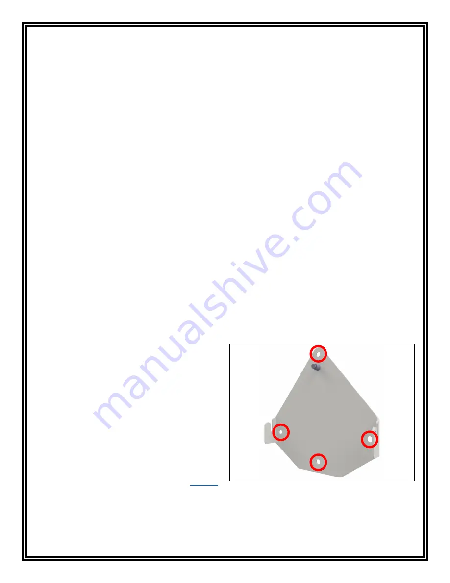
5. Use the included screws and anchors to secure
the mounting bracket to the desired location. The
screws may be used in any of the four holes shown
below. Be sure to locate the bracket where users
can read the display and use the tester.
Figure 4. Mounting holes on the SmartLog Pro™
mounting bracket


