Functional Description
ATCA-F120 Installation and Use (6806800D06F
)
94
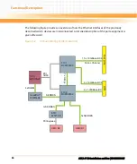
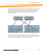
At the same time, port 0 of the Update channel is used for a connection to the CPU of the
partner ATCA-F120 in the system. The following figure illustrates this configuration.
4.10 Intelligent Peripheral Management Controller
The blade provides an Intelligent Peripheral Management Controller (IPMC) unit based on
three Atmel ATmega AVR micro controllers. One micro controller, the Atmega2561V serves as
IPMC Master Controller (IMC) and provides an on-board flash memory of 256 KBytes. The
remaining two micro controllers, both are Atmega168L devices, serve as IPMC Slave
Controllers (ISC) and provide an on-board memory flash memory of 168 kBytes each. Both are
referred to as ISC0 and ISC1.
An installed RTM furthermore provides an Mezzanine Management Controller (MMC) which is
connected to the IPMC through an IPMB-L bus. The MMC contains an Atmega 128L micro
controller. For details about the MMC refer to the documentation delivered with the respective
RTM.
Figure 4-5
Shelf Manager Cross Connection via Base Channel
Shelf Manager #1
Shelf Manager #2
ETH#1
ETH#2
ETH#1
ETH#2
A5 - D5 E5 - H5
Base Channel #1
A5 - D5 E5 - H5
Update Channel #0
ATCA-F120 in Hub Slot #1
A5 - D5 E5 - H5
Base Channel #1
A5 - D5 E5 - H5
Update Channel #0
ATCA-F120 in Hub Slot #2
CPU
CPU
Summary of Contents for ATCA-F120
Page 6: ...ATCA F120 Installation and Use 6806800D06F Contents 6 Contents Contents ...
Page 8: ...ATCA F120 Installation and Use 6806800D06F 8 List of Tables ...
Page 10: ...ATCA F120 Installation and Use 6806800D06F 10 List of Figures ...
Page 18: ...ATCA F120 Installation and Use 6806800D06F About this Manual 18 About this Manual ...
Page 24: ...ATCA F120 Installation and Use 6806800D06F Safety Notes 24 ...
Page 120: ...U Boot Firmware ATCA F120 Installation and Use 6806800D06F 120 ...
Page 124: ...Index ATCA F120 Installation and Use 6806800D06F 124 ...
Page 125: ......


