Hardware Preparation and Installation
ATCA-F120 Installation and Use (6806800D06F)
49
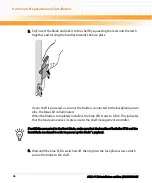
When the blue LED is switched OFF and the green LED "OK" is switched ON, this
indicates that the blade`s payload has been powered up and that the blade is
active.
7. Connect cables to the face plate, if applicable.
2.6.2
Removing the Blade
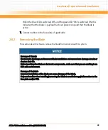
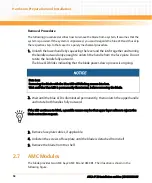
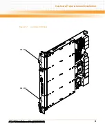
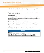
This section describes how to remove the blade from an AdvancedTCA system.
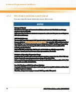
Damage of Circuits
Electrostatic discharge and incorrect blade installation and removal can damage circuits or
shorten their life.
Before touching the blade or electronic components, make sure that you are working in an
ESD-safe environment.
Damage of the blade
Incorrect installation of the blade can cause damage of the blade,
Only use handles when installing/removing the blade to avoid damage/deformation to the
face plate and/or PCB.
Summary of Contents for ATCA-F120
Page 6: ...ATCA F120 Installation and Use 6806800D06F Contents 6 Contents Contents ...
Page 8: ...ATCA F120 Installation and Use 6806800D06F 8 List of Tables ...
Page 10: ...ATCA F120 Installation and Use 6806800D06F 10 List of Figures ...
Page 18: ...ATCA F120 Installation and Use 6806800D06F About this Manual 18 About this Manual ...
Page 24: ...ATCA F120 Installation and Use 6806800D06F Safety Notes 24 ...
Page 120: ...U Boot Firmware ATCA F120 Installation and Use 6806800D06F 120 ...
Page 124: ...Index ATCA F120 Installation and Use 6806800D06F 124 ...
Page 125: ......

