Hardware Preparation and Installation
ATCA-F120 Installation and Use (6806800D06F
)
52
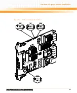
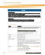
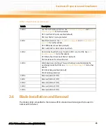
The following sections describe which type of AMC modules are supported for each AMC bay.
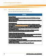
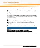
Furthermore, the installation/removal procedure for AMC modules will be given. This
procedure is identical for all AMC modules in both AMC bays.
2.7.1
Supported AMC Modules
The AMC bays AMC B4 and AMC B1 are designed to support different types of AMC modules.
Both AMC bays are compliant to AMC.0 R2.0.
2.7.1.1
AMC Bay B4
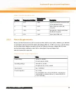
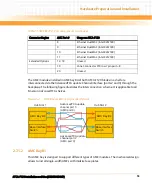
This AMC bay is designed to support Emerson processor AMC modules. The following table
describes how the AMC ports are assigned.
Consult your local Emerson sales representative for a list of AMC modules which Emerson has
validated for the use in AMC B1 and AMC B4.
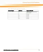
Table 2-5 AMC Bay B4 - Port Assignments
Connector Region
AMC Port #
Usage on ATCA-F120
Clocking
1
Unused
2
Unused
3
PCI Express HCSL 100 MHz clock
Common Options
0
AdvancedTCA update channel port 2/3
1
AdvancedTCA update channel port 4
2
AMC Bay B1 port 2
3
AMC Bay B1 port 3
Fat Pipes
4
AMC Bay B1 port 4
5
AMC Bay B1 port 5
6
AMC Bay B1 port 6
7
AMC Bay B1 port 7
Summary of Contents for ATCA-F120
Page 6: ...ATCA F120 Installation and Use 6806800D06F Contents 6 Contents Contents ...
Page 8: ...ATCA F120 Installation and Use 6806800D06F 8 List of Tables ...
Page 10: ...ATCA F120 Installation and Use 6806800D06F 10 List of Figures ...
Page 18: ...ATCA F120 Installation and Use 6806800D06F About this Manual 18 About this Manual ...
Page 24: ...ATCA F120 Installation and Use 6806800D06F Safety Notes 24 ...
Page 120: ...U Boot Firmware ATCA F120 Installation and Use 6806800D06F 120 ...
Page 124: ...Index ATCA F120 Installation and Use 6806800D06F 124 ...
Page 125: ......


