Hardware Preparation and Installation
ATCA-F120 Installation and Use (6806800D06F
)
58
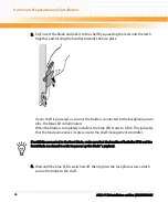
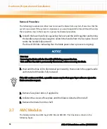
The blue LED blinks when the handle is locked in position indicating module
detection and activation by the carrier board.
10.Observe blue LED status/activity. The module is fully installed when the blue LED
stops blinking and stays OFF.
Removal Procedure
The following describes how to remove an AMC module from the ATCA-F120. The procedure
assumes that the ATCA-F120 is powered. If it is not powered, the steps regarding the blue LED
can be ignored and skipped.
1. Make sure you are in an ESD safe environment.
2. Remove any cables that are connected to the AMC module face plate connectors.
3. Gently pull the module latch outwards, approximately 3mm from its locked
position.
4. Wait for the blue LED to first perform short blinks, and then glow persistently.
Data Loss
Removing the blade with the blue LED still blinking causes data loss.
Wait until the blue LED is permanently illuminated, before removing the blade.
Summary of Contents for ATCA-F120
Page 6: ...ATCA F120 Installation and Use 6806800D06F Contents 6 Contents Contents ...
Page 8: ...ATCA F120 Installation and Use 6806800D06F 8 List of Tables ...
Page 10: ...ATCA F120 Installation and Use 6806800D06F 10 List of Figures ...
Page 18: ...ATCA F120 Installation and Use 6806800D06F About this Manual 18 About this Manual ...
Page 24: ...ATCA F120 Installation and Use 6806800D06F Safety Notes 24 ...
Page 120: ...U Boot Firmware ATCA F120 Installation and Use 6806800D06F 120 ...
Page 124: ...Index ATCA F120 Installation and Use 6806800D06F 124 ...
Page 125: ......

