DATAPLOT GmbH
Gutenbergstraße 15
24558 Henstedt-Ulzburg
Germany
Telephone: +49 4193 995-0 Fax: +49 4193 995-220
[email protected]
www.dataplot.de
Page 1 / 28
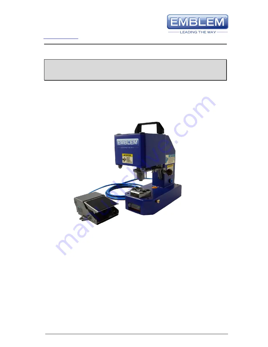
EASY AIRPRESS
Standard 4 FP
Pneumatic Airpress
>
USER'S MANUAL
Version 1.1
Page 1: ...Gutenbergstra e 15 24558 Henstedt Ulzburg Germany Telephone 49 4193 995 0 Fax 49 4193 995 220 support dataplot de www dataplot de Page 1 28 EASY AIRPRESS Standard 4 FP Pneumatic Airpress USER S MANUA...
Page 2: ...3 Installation of the die for metal eyelet 8 3 4 Installation of the die for plastic eyelets 10 3 5 Compressed air connection 13 3 6 Optional accessories 13 3 7 Installation of the optional trolley 14...
Page 3: ...s disconnect the device from the compressed air supply before performing the following work on the machine Changing the dies Cleaning adjustment or maintenance Repairs The outlet pressure of the compr...
Page 4: ...less you have read and understood the User s Manual Failure to do so jeopardises your health Caution Only qualified technicians may adjust the finger guard Danger Do not remove this part Finger guard...
Page 5: ...to transparent 12mm plastic eyelets With both the plastic dies and the metal dies the cut out parts of the banner are pressed through the upper die into a practical collecting container which can be...
Page 6: ...ard 9 Footpedal 2 4 Technical data Device description EMBLEM Easy Airpress Standard 4FP Safety system Sensor controlled finger guard Compressed air supply 8mm directly connected Operating pressure 5 7...
Page 7: ...3 995 220 support dataplot de www dataplot de Page 7 28 3 Installation 3 1 Scope of delivery 1 Footpedal 2 Handle 3 Open end spanner 4 Allen wrench 4mm 5 Allen wrench 3mm 7 M5x16 screw 8 A5 3 washer 9...
Page 8: ...handle Screw the handle onto the upper side of the device 3 3 Installation of the die for metal eyelets 1 Remove the compressed air hose For the remainder of the installation procedure there must be n...
Page 9: ...Turn the upper die all the way into the adapter nut and tighten with the fingers 5 Loosen the right screw for the lower die with a screwdriver 6 Turn out the screw until it is no longer visible in th...
Page 10: ...ure there must be no pressure on the device 2 Remove the adapter nut using the open end spanner The adapter nut is not required for this die Save the adapter nut for later use with a die for metal eye...
Page 11: ...n out the screw until it is no longer visible in the hole 7 Insert the lower die into the hole and press up to the stop 8 Tighten the screw for the lower die 9 Loosen the two front screws on the lower...
Page 12: ...letely into the lower die and control that the upper die is centred in the lower die without snagging 13 Connect the compressed air hose 14 Drive the finger guard with the manual operation lever slowl...
Page 13: ...an 7 bars can damage the device and cause serious injuries to the operator The device operates with a pressure of 5 7 bars It is designed to give the best results for an air pressure of 6 bars Permane...
Page 14: ...4193 995 0 Fax 49 4193 995 220 support dataplot de www dataplot de Page 14 28 3 7 Installation of the optional trolley 1 Remove the four blue stickers over the drill holes 2 Remove the four plastic fe...
Page 15: ...ed air hose not supplied and attach it to the angular piece supplied 5 Attach the other end of the 25mm long hose to the connection on the device 3 8 Installation of the optional LED pointer 1 Prepare...
Page 16: ...t points to the centre of the punched section 5 To adjust towards the front and rear rotate the bracket in the horizontal plane 6 To adjust towards the left and right rotate the pointer The Phillips h...
Page 17: ...y compartment remove the locking screw 2 Then insert a flat screwdriver into the mount and carefully rotate 3 The cover should then lift on this side 4 Pull the cover in the direction of the arrow A a...
Page 18: ...de www dataplot de Page 18 28 3 10 Installation of the optional spacer 1 Remove the yellow sticker and the upper and lower dies 2 Remove the left screw 3 Position the spacer so that pins A B and C fi...
Page 19: ...mpressed air hose For the remainder of the installation procedure there must be no pressure on the device 2 Actuate the manual operating lever to drive the finger guard downwards Loosen the upper die...
Page 20: ...and remove the die Continue as described from Step 2 in Section 3 3 4 2 Plastic eyelets plastic eyelets 1 Remove the compressed air hose For the remainder of the installation procedure there must be...
Page 21: ...emove the die Continue as described from Step 3 in Section 3 4 4 3 Metal eyelets plastic eyelets 1 Remove the compressed air hose For the remainder of the installation procedure there must be no press...
Page 22: ...Fax 49 4193 995 220 support dataplot de www dataplot de Page 22 28 4 Loosen the right screw for the lower die with a screwdriver 5 Remove the punch waste collecting container Press the lower die upwa...
Page 23: ...ose For the remainder of the installation procedure there must be no pressure on the device 2 Actuate the manual operating lever to drive the finger guard downwards Loosen the upper die with the open...
Page 24: ...dataplot de www dataplot de Page 24 28 5 Actuate the manual operating lever to drive the finger guard downwards Slide the adapter nut for the upper die over the finger guard and turn it into the uppe...
Page 25: ...ularly after changing the dies or following unsatisfactory punching results Faulty adjustment can damage the dies 5 1 Die for metal eyelets 1 Remove the compressed air hose For the remainder of the in...
Page 26: ...position 5 2 Die for plastic eyelets 1 Remove the compressed air hose For the remainder of the installation procedure there must be no pressure on the device 2 Actuate the manual operating lever to d...
Page 27: ...the lower bracket 6 Slide the upper die several times completely into the lower die and control that the upper die is centred in the lower die without snagging 7 Connect the compressed air hose 8 Slow...
Page 28: ...Rotating in the clockwise direction reduces the speed This adjustment affects only the use of the footpedal 6 CE Declaration of Conformity We the DATAPLOT GmbH Gutenbergstra e 15 24558 Henstedt Ulzbur...