Page 8 of 10
Firmware V0.5.0
Revision 3
BU-091 - 008TCWE
Water Comfort System · Operating Manual Electronic Temperature Control Unit ELTC-W
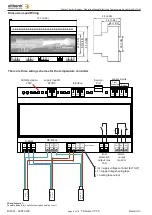
2
3
0
V
m
a
x C2
0
A
Con
tr
o
lle
r
Cur
re
n
t
47
(
1.8
5)
63
(
2
.4
8
)
93
(
3.6
6)
E
L
S
R
-W
...
Hea
tin
g
T
ape
35
(
1.38
)
Dimensions and Wiring
153 (6.02)
59 (2.32)
39 (1.54)
26 (1.02)
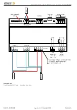
There are three wiring schemes for the temperature controller.
LED-Operation
230V
supply input B
24VDC
Interface
Service-
Port
sensor inputs
Frost
Protection
Boiler
(-)
(+)
DO NDO Gnd
Gnd F1 Gnd F2
2 A
N-Block
PE-Block
N
N
N
PE PE PE
L(A) L1
L1
L (heating tape)
Com NO
Com NO NC
frost
protection
output max
16 A
alarm-
output
max 2 A
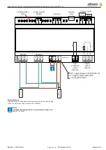
L(A) = supply voltage controller (ELTC-W)
L1 = supply voltage heating tape
L = heating tape output
Wiring Scheme 1:
Separate feeders for controller device and heating circuit.


