eltherm 0630000 Operating Manual Download Page 2

Water Comfort System · Operating Manual Electronic Temperature Control Unit ELTC-W


Page 2 of 10   

Firmware V0.5.0


Revision 3


BU-091 - 008TCWE


Circulation Pipe 

Electrical Heat Tracing


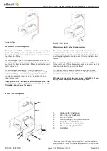
Warm water circulation system


This system consists of the warm water boiler, warm water pipe, 
pump, valves, fittings, and a circulation pipe that is used for 
temperature maintenance. The pipes are soldered or pressed 
together using fittings.


A circulation pipe does not provide warm water all the way to


the water outlet.  A waste of water takes place because the user 
must wait until the cold water has left the pipe before the warm 
water comes out.


A circulation pipe requires more room for installation,


it is more expensive to install (e.g. cutting the pipe to length, 
soldering of fittings, more time = paying installers, etc) and 
requires maintenance (e.g. Valve or its seal, and the pump 
need replacement)


The operation of a circulation system requires more ener- 
gy. (Increased surface and hence increased heat loss due 
to double piping; power for pump.)


Warm water electrical heat tracing system


This system uses the same principle as the warm water cir- 
culation system but does not require a circulation pipe, pump, 
valves and fittings associated with the circulation pipe. Instead 
a self-regulating heating cable is used for temperature mainte- 
nance.


With electrical heat tracing warm water is provided all the way


to the water outlet. This saves water because the warm water is 
readily available when opening the faucet.


This system requires less room because the heating cable is 
placed directly on the warm water pipe. So it is less expensive 
to install. It does not require maintenance.


With electrical heat tracing you can save up to 65 % of your 
energy costs compared to a circulation system.*


Water Comfort System


2


5


Insulation (by Customer)


Water pipe (by Customer)


EL-Clic T-splice


Self-regulating heating cable ELSR-W


Self-adhesive aluminum foil


EL-Clic fast connector system


Water boiler (by Customer)


Controller


3


4


8


* Exemplary system: 1/2 " piping, heated length 10m, 15 mm thermal insulation,


power consumption of pump 75 W, maintain temperature 45°C, ambient tempera-


ture 15°C.


Summary of Contents for 0630000

Page 1: ...using The eltherm Water Comfort System provides the energy saving solution to keep warm water steadily available and to fight legionella bacteria effectively Advantages of the eltherm Water Comfort System for you High user friendliness by intuitive adjustment Simplified entry A lot of details are already preset for choice Logical and clear composed menu no confusing icons Complicated calculations ...

Page 2: ...ss due to double piping power for pump Warm water electrical heat tracing system This system uses the same principle as the warm water cir culation system but does not require a circulation pipe pump valves and fittings associated with the circulation pipe Instead a self regulating heating cable is used for temperature mainte nance With electrical heat tracing warm water is provided all the way to...

Page 3: ...undeinstellungen Base Settings RET select a parameter list select parameter to be programmed RET start programming parameter name blinks ESC Optionally an identification is required choose settings keeping cursor button pushed accelerates the display of data ELTC W 10 49 WE 2 Setup RET Sollwerte Einstellung Settings RET end programming ESC brings you back to list overview ESC ELTC W 10 50 WE 3 Tim...

Page 4: ...andard busbar 35mm IP 20 Danger It presents a danger to life A safe operation might not be possible if the device has visible damage the device does not work after longer storage in inappropriate conditions contamination or humidity after hard transport stress Installation and operation of the device must be carried out by a certified electrician or under observation by a certified electrician Kee...

Page 5: ...e time On the daily date switch 23 59 0 00 the output is operated for a deter mined time of 2 hours for legionella bacteria reduction with 100 power On the display the remaining time round up number of days with a maximum of 99 days is shown which means if the remaining time is under 24 hours the display shows 1 day Frost Protection By setting the parameter ActivateA F the frost protection functio...

Page 6: ...mum expected temperature at pipe location The diameter of water pipe The thickness of insulation Can be used to adjust the internally calculated power output to local conditions If the Trace Boiler function is activated the ELTC W will follow the temperature of the boiler Therefore a temperature sensor is needed at boiler surface If boiler probe detects this temperature or above legionella protect...

Page 7: ...1 08 00 Uhr Maint temp 2 08 01 11 00 Uhr Economy Mode 1 11 01 13 00 Uhr Maint temp 2 13 01 16 00 Uhr Economy Mode 1 16 01 22 00 Uhr Maint temp 2 22 01 23 59 Uhr No heating 0 enter menu ELTC W 10 49 WE Standard mode Standard Display Restaurant 00 00 02 00 Uhr Economy Mode 1 02 01 03 00 Uhr Legionella protection 3 03 01 06 30 Uhr No heating 0 06 31 08 00 Uhr Economy Mode 1 select function Timer pres...

Page 8: ...ere are three wiring schemes for the temperature controller LED Operation 230V supply input B 24VDC Interface Service Port sensor inputs Frost Protection Boiler DO NDO Gnd Gnd F1 Gnd F2 2 A N Block PE Block N N N PE PE PE L A L1 L1 L heating tape Com NO Com NO NC frost protection output max 16 A alarm output max 2 A L A supply voltage controller ELTC W L1 supply voltage heating tape L heating tape...

Page 9: ...Gnd Gnd F1 Gnd F2 2 A N Block PE Block N N N PE PE PE L A L1 L1 L heating tape Com NO Com NO NC Advice frost protection output max 16 A alarm output max 2 A L A supply voltage controller ELTC W L1 supply voltage heating tape L heating tape output Wiring Scheme 2 If the heater and the temperature controller are connected on same feeding circuit the system has to be protected with C 20A max Advice A...

Page 10: ...terface Service Port sensor inputs Frost Protection Boiler supply input B 24VDC DO NDO Gnd Gnd F1 Gnd F2 2 A N Block PE Block N N N PE PE PE L A L1 L1 L heating tape Com NO Com NO NC frost protection output max 16 A alarm output max 2 A L A supply voltage controller ELTC W L1 supply voltage heating tape L heating tape output Wiring Scheme 3 Connect separate 24 VDC supply for controller as shown ab...

Reviews: